SigmaStudio 4.7 bug with Indirect Parameter Access Table using "Signal Invert" IC block
We are building a self-powered single driver (stereo mixed to mono) subwoofer using an ADAU1452 and SigmaStudio 4.7 to build our DSP. In order to create the typical subwoofer phase 0/180 feature, I added a "Signal Invert" IC block and then performed an "Add Algorithm" such that the Signal Invert block can support two (stereo) channels. This block functions fine using the schematic interface in SigmaStudio. I can toggle the single check box and the phase is shifted and the audio sounds normal. Note that the subwoofer uses analog hardware to mix the stereo channels into a single mono channel for the amplifier.
Because we are toggling DSP options via I2C using an MCU, I have added all the I2C controlled blocks to the Indirect Parameter Access Table. When I add the Signal Invert block, I noticed that the Indirect method only toggles one of the two channels. This is easily seen in the I2C output of SigmaStudio. The actual schematic block writes to two subaddress, but the Indirect only writes to one of the two subaddresses. Sure enough, when I use it while listening to the subwoofer toggling via Indirect causes phase cancelation which is a total deal-breaker.
Based on my experience writing software this presents as a true bug in SigmaStudio that will require a patch to fix. I am working on a product that is road-mapped for an end of 2023 release date so I need a fix urgently. This is a high priority issue and highly visible due to it being a direct customer used feature of the product.
Audio Signal Processors
adau1452
sigma studio
Audio Products
software
4.7
sigmastudio
SigmaDSP Audio Processors
SigmaDSP
Show More
Hello compy386,
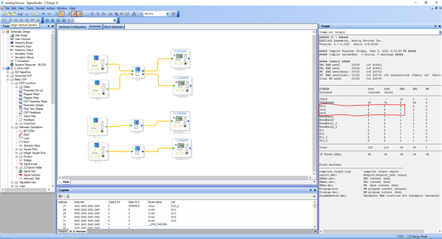
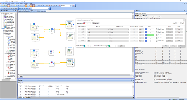
I could see that in the capture window there are two addresses for the two-input (grown by one) invert block. In the schematic, when you check/uncheck the box, both addresses will be written '1' or '0' respectively at the same time. However, you can directly write to both addresses individually in the capture window. But in the IPAT, as you said there is only one address that is shown. The same thing is happening with a grown mute block etc. Since the channels are grown it will have a single access in the GUI, so it will be easy to mute/unmute or invert/non invert all the channels at once. However, you can access the addresses individually in the capture window as I mentioned earlier. It would've been easier if all the individual addresses are shown in the IPAT window. Now only one address is shown in the IPAT and by changing that will only affect one channel path of the two-channel invert block.
A solution I can think of is that, why don't you use two different invert blocks. Both two channel invert block (grown by one) and two individual invert blocks will cost the same MIPS and the memory as you can see below.
It may sound simple but by doing this you will have access to both the address in the IPAT as shown below. Is that what you want?
Regards,
Harish
Harish,
Thanks for reproducing the bug. I considered the option you proposed of making multiple invert blocks instead growing. However, I'm in a situation where I am responsible to manage the SigmaDSP firmware as well as the other firmware for this product. We have a dedicated audio engineer that is creating the actual DSP and I am trying to integrate and test it with our other firmware. I would really prefer that the "grow algorithm" feature would work properly with IPAT for the invert feature as well as the other features (mutes, etc.). As our DSP grows in complexity, I really want to avoid work-arounds.
Do you have the ability to check the reported bugs against 4.7 for this issue, and/or how would I go about getting this bug reported against SigmaStudio.
Thanks,
Peter
Hello Peter and Harish,
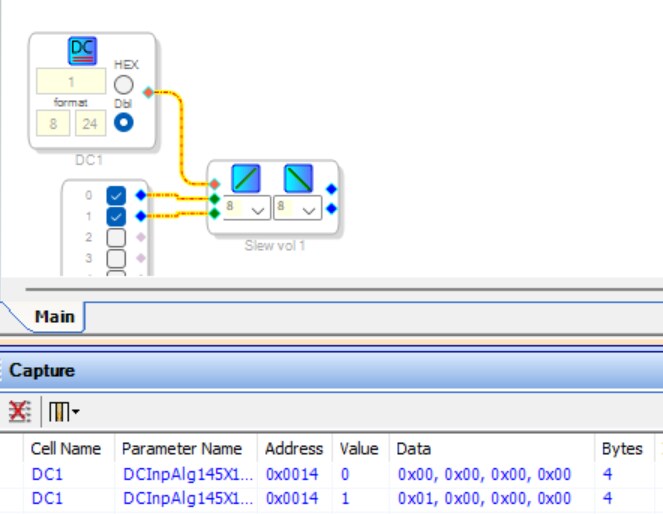
Another workaround is to have a DC source control a Slew Volume Control to achieve the mute function, then write via I2C to that DC source:
Edit: Sorry I didn't notice that you need an invert, not a mute. You could have the DC Source feed a pair of multipliers to invert the signals or not (simply load the source as -1.0 or +1.0, respectively). The mixer developed where I work has six ADAU1701s (for which the indirect parameter table isn't available), so we found this method handy for setting all sorts of functions. The addresses for DC sources often get placed low in parameter memory, thus the many inevitable revisions rarely disturb them.
Best regards,
Bob
Please log in to reply.