USBi programmer behaving abnormally
Hello,
I am using USBi with SigmaStudio v4.7. I also have ADAU1701 mini eval board, and my own target board with ADAU1701, EEPROM socket and USBi interface header.
The discription of the issue is as follows:
If I plug the programmer with the target board connected or the eval board connected, then, all the status LEDs on the USBi remain lit and the hardware configuration tab in the signaStudio remains red.
If I plug the USBi programmer into the USB port of my PC (Windows 10) without the target board, then the USB status in the hardware configuration tab of SigmaStudio turns green. All the status LEDs on the USBi light up briefly and then only the power LED and I2C LED remain lit. The SPI LED and the blue LED turn OFF
If I plug the USBi programmer into the USB port of my PC without the target board, with the USB status in the hardware configuration tab of SigmaStudio green and only the power LED and I2C LED remain lit and then connect the ADAU1701 eval board to the USBi, then two red LEDs next to the push switches, one red LED near the 3.5mm audio connector and one green LED to the right of it all light up.
In any case, I am unable to program the EEPROM either on the target board or on the eval board. The SigmaStudio flashes USB communication error message.
Kindly advice.
Thanks!
Hello KKSL,
It certainly seems like something is wrong with the USBi.
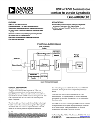
Here is an old datasheet with the schematic. It might not be 100% up to date with the one you have but it is a start. I would suspect the regulators. Also, make sure the switch on the bottom is set to 3.3V.
Dave T
The IOVDD switch is in 3.3V position.
The hardware looks ok to me.
Voltage across C22 (5V0DD) is 4.87V, across C14 (3.3V reg) is 3.24V, across C13 (1.8V reg) is 1.77V. This is irrespective of whether the USBi is powered up with the header unconnected (blue LED off), or whether the USBi is powered up with the target board connected (blue LED is ON).
I also checked the voltage at the target power switch.
With no fault, voltage across R14 (USB_PWR_ON) is 3.24V), Q1-C (5V0DD_USB) is 4.34V
With fault, voltage actoss is R14 is 0.03V and across Q1-C is 0.78V
Kindly help me debug this further.
Thanks!
It was the dual SPST switch, ADG721. I replaced it and the programmer is restored back to its original functionality.
I don't know why the part could have failed. I have been using the progammer for 20+ years tough. It could be some sort of sub-atomic wear and tare, if at all anything like that exists.
Please log in to reply.