adau1701 clocks configurations
Hello dear engineers!
I'm working on a project with ADAU1701, with an external main microcontroller that provides all the clocks to the DSP. I'm using TDM subordinate mode with a 1024 instructions length.
According to the ADAU1701 datasheet for a 44.1kHz audio mode, MCLKI should be 11.2896MHz, PLL_MODE0 should be connected to GND, and PLL_MODE1 to VCC. Also, BCLK should generate 256 pulses for an 8-channel TDM, 32 pulses for each channel (slot). This means that BCLK should be 256 * 44.1 = 11.2896MHz for me.
However, in reality, it doesn't work for me this way. I only get proper DSP behavior when I set MCLKI to twice 11.2896MHz, which is 22.5792MHz, and BCLK remains at 11.2896MHz. But shouldn't PLL_MODE1 and PLL_MODE0 be connected to VCC to work with a 22.5792MHz MCLKI? Am I missing something important, or are all parameters okay?
With the configurations mentioned above as the working setup (MCLKI 22.5792MHz and BCLK 11.2896MHz), there is still strange sound behavior. I'm reading mono WAV files from an SD card with a main microcontroller, and if I send them directly to the DSP via TDM, there is a lot of sound distortion, as if it's going over a threshold. But if I reduce the file volume to at least 30% before sending it to the DSP via TDM, everything sounds just fine.
Providing pictures of my SigmaDSP setup.
Hope fore some clarification, thank you, best regards, Roman!
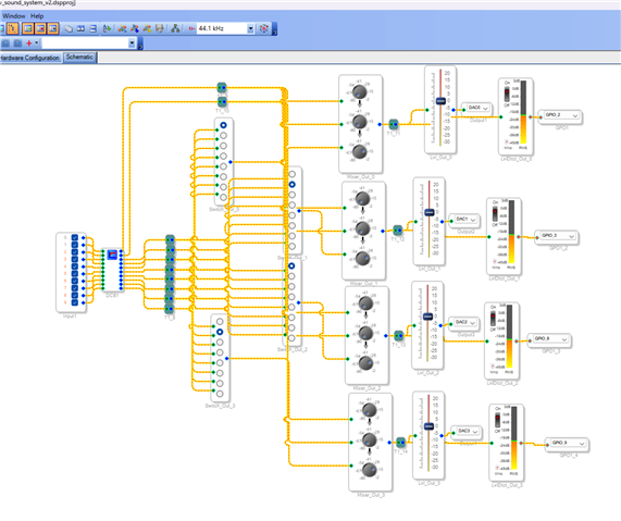
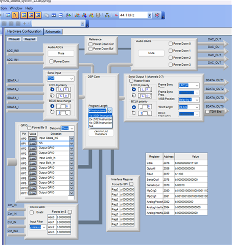
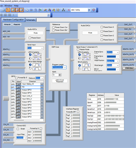
Hello,
You're correct about the PLL -- with its pins set to (1,0), MCLK should be 11.2896 MHz. Since the chip appears to operate better when overclocked at 22.5792 MHz, I'm wondering about the timing of all your I2S signals. Have you scoped your BCLK, LRCLK, and TDM data signals to see how they compare to the data sheet requirements? One of the products made where I work uses TDM for both input and output of six ADAU1701s. The difference here is that the -1701s connect to each other, thus it's no surprise that the timing of all these signals is compatible.
Best regards,
Bob
Hello Roman,
By the way, thanks for signing your name. I like to have these interactions be more human than a user name.
I agree with Bob that you have the correct pin settings for a 256x fs master clock with PLL_MODE0 low and Mode1 tied high.
But how do you know the clocks coming out are wrong when you are supplying the clocks to the serial port? The DSP serial input port is always a slave.
But I guess you said proper "behavior" and not clock rates.
I did notice the RAM Modulo setting is set to 12. I usually see this set to 8 and it is something you should never change and it really should not have been a register or should have been a hidden register. Let the compiler set it and do not change it. Set it to 8 and see if that helps.
Then you might want to look at how your microcontroller is formatting the data in the 32 bit slot. I think it is right justifying the data which would mean that the DSP is ignoring the upper 8 bits which includes the sign bit. So the audio will be very bad until the level drops below 16 bits of resolution then all of a sudden the sign bit will be correct and the data will be properly interpreted.
The data needs to be left justified and delayed by one bit clock period from the falling edge of the LR clock. That is what you have set in the TDM format options.
I suggest you use a scope to see how the data is formatted coming out of your controller.
Dave T
Hello, Bob and Dave.
Thank you very much for your replies, and sorry for me taking so long to continue this conversation.
I'm sorry, Dave, didn't know that there is no name singed on my previous posts...
I've changed memory setting to 8 as you suggested, Dave, nothing had changed yet.
From the main microcontroller I'm sending 16 16 bits slots, but skipping every even slot, so it should be left justified, also I've had configured STM SAI to delay data by one bit according to adau's data sheet.
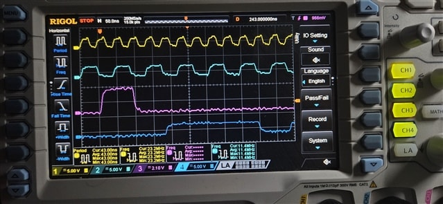
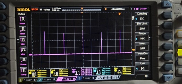
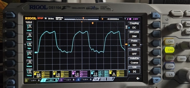
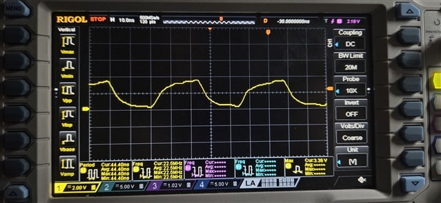
Here some oscilloscope measurements of all my signals from main microcontroller:
Close view on clock signals:
FS/LRCLK
BCLK
MCLK
Update:
I've just tested to provide 11.2896MHz MCLK from main microcontroller to adau, and adau even doesn't respond on i2c bus, but when I'm going back to 22.5792MHz MCLK, i2c starts to respond and all my commands via i2c work just fine.
Another thought - I'm sending i2c commands from second microcontroller, not from the main that is providing MCLK, so maybe the problem is no synchronization between two microcontrollers and no synchronization between second microcontroller and adau in i2c communication, but still, with 22.5792MHz MCLK i2c does work well...
Best regards
Roman
Please log in to reply.