Pin output sequence for power on and shut-down amplifier section
Hi guys.
I would like to make a logical sequence to turn on the amplifier section with my 1701s. When I generate the start pulse (I use the encoder button) I need two outputs. The first output goes high immediately (power supply) and the second after a few seconds (relais output) but when I generate the shutdown pulse I need the opposite sequence, so the second must go low and then the first after a few seconds.
With two toggle on/off and two timers with DC input I managed to do the switch-on sequence, I have difficulty with the switch-off sequence.
Thank you
Stefano
Audio Signal Processors
dsp
Audio Products
software
adau1401
Sigma Studio 4.6
delay time
sigmastudio
SigmaDSP Audio Processors
gpio
ADAU 1701 1401
adau1701
Show More
Hello Stefano,
Please try the below attached project.
I don't have ADAU1701 core in my hand, So In order to check the logic, I have implemented and run it with sigma350 core (latest), you please copy the logic for the ADAU1701.
Adjust the DC blocks for the delay required (in samples).
Pin output sequence.dspproj
Hope this helps.
Regards,
Harish
Hi Harish,
Thanks for the reply.
The 1701 does not have an "arithmetic shift" but your schematic is correct.
I added an input pin controlled toggle block and it works fine.
I solved the amplifier start sequence!
But when I turn on the power the sequence starts without pressing the button.
If you have an idea to solve this problem I would be happy.
Have a nice day.
Stefano
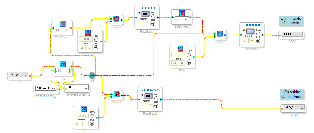
Hello Stefano,
Please find the attached project. I hope it will work as you asked for.
Pin output sequence v1.dspproj
Regards,
Harish
Please log in to reply.