Sample delay for each functional block in Sigma Studio
Hi,
I am looking for more detail about the implementation of each block outside of what the wiki supplies. I am specifically looking for sample delay of the signal in a block, if any. Some blocks I of course expect some amount of delay based on parameters entered.... but how about delay because of implementation in each block?
Consider a case where two time synchronized signals come in two inputs. One has many stages of processing and then an output. The other just a delay to line up the signals again. It would be nice to be able to calculate rather than use a scope to line up the signals again using the delay on the second channel.
Is there any place I can find this kind of information? As the algorithms are not available to us, it is impossible to characterize outside of using a scope and signal source (which is what I've been doing).
Thanks
Tom
software
4.7
sigmastudio
Hello Tom,
Good questions. The answer will depend somewhat on the specifics of which blocks you are using. That said, here is a general answer for most of the blocks and a starting point of our discussion.
The SigmaDSP is a stream based processor. This means that when the program is triggered to run, It will process "one sample" and then deposit the result to be passed out of the core. Then it will wait to be triggered again.
I put the quotes around "one sample" because if you have 48 inputs it will process the 48 new samples not just one of them at a time. But for each signal path it will take one sample at a time. The entire program schematic you draw in SigmaStudio is executed EVERY sample period. The entire schematic. Blocks will not cause any delay unless that is its job. Let me use a simple example that someone once asked me on the forum.
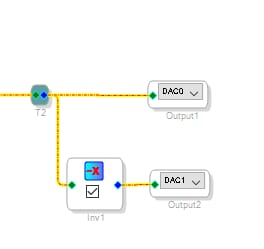
Take this circuit where someone wants to use two DAC outputs as a differential output. So they do this:
I was asked how much phase shift does this add? Since I am old enough to know about good old analog design I understand why he was asking! Any OpAmp will add some delay. In this case the delay is zero. Because the program will deposit the output sample into the memory location of DAC0, Then it will invert the sample and then deposit the inverted sample into DAC1 memory location. Then the program completes its processing and waits for the next sample period to start. When the next sampler period starts, the serial output port will pick up BOTH words and shift them out. No delay at all. So if you run one signal through a lot of blocks and one you bypass, they will not be shifted in phase at all as long as the blocks do not add delay because of their function. This is where the specifics become important.
If you put one through an IIR EQ and boost or cut it a lot and do not do it to the other channel then you will get a phase shift because the EQ equation will add some phase shift. Many years ago at a University I used to demonstrate in a studio why you should EQ both channels of stereo signals the same amount to avoid adding phase shift differently on each channel. So that all still applies here. Most of the EQs are Bi-Quads and so they are IIR filters. We do have some FIR filters and you can import your own coefficients to make them linear phase but then you will get the group delay of the FIR filter. All of this is nothing new as far as audio theory so this is why we do not mention this in the Wiki pages. SigmaStudio itself will not introduce any delays channel to channel unless you add a delay block yourself. All the inputs are processed and completed every sample period.
By the way. The trigger to start the program running is called the Start Pulse and that is selectable in the Sigma200 and Sigma300 cores. The old Sigma100 (ADAU1701) does not have the ability to choose a different start pulse. It will use its internal clock divided down from the master clock input.
Depending on what you are doing and how sensitive your application is, It would still be a good idea to check the phase like you have been.
I hope this helps.
Dave T
Hi Dave,
You've confirmed in your great overview a few things I determined experimentally. There is something to be said for actually being exposed to the architecture rather than it being hidden behind a gui!
I already figured out that all basic parts and connections are actually graph traced by the compiler to line up dependencies of inputs to subsequent common stages. For example, a signal teed to a single stage and also a chain of multiple stages, if those two streams then meet (say) at an adder, it gets the results of both graph branches completed before doing the adder. Made sense it should work that way to allow operation as you describe.
The significance of the start pulse also made sense. I run my start pulses at 2x for 96khz and sync everything to that.
I'm more interested in stages that have memory effects. As I've written signal processing for many dsp's as well as generic cpu's, some architectures with how they do array like operations with post/pre inc/dec operations work better if the first sample processed is not the one at the input to the algorithm, but rather, the first one in the memory queue. The current input then becomes the next one after a shift (usually done by index addition/modulus, etc, etc, arch specific). This detail is important to me. I've been skirting it by checking alignment myself. This kind of sample delay is often found in implementations FIR and IIR depending on programmer, algorithm and architecture. It is this that I am looking for. This is outside of the delay added by the actual processing of the filter itself (the group delay of the calculated filter).
If in all cases it is always including the current input value as a part of the calculation of such multiple sample algorithms, that makes it easy as the group delay of the functions my coefficients produce is already taken care of in my calculations.
In any case, this is why I'm wondering what stages have a sample delay vs all the others that don't.
Thank you
Tom
Please log in to reply.