AD1953 Interesting SPI Behavior
Hello, I have an AD1953 project that I'm working on and have a question about how certain values are handled for SPI writes in certain scenarios. I am working on an amplifier/speaker project in which the speaker configuration is being changed which requires different x-over etc. In an effort to learn more, I have taken a look at the current communication to the IC leading to my question...
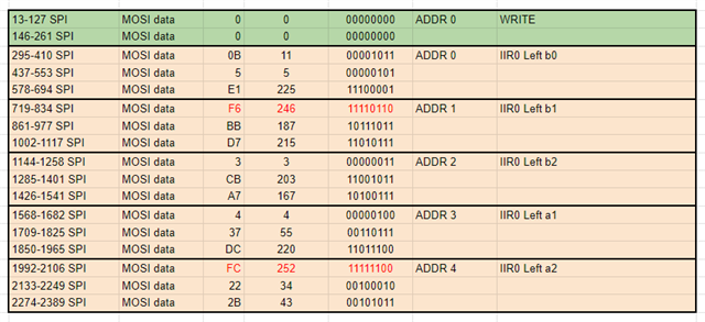
The attached image shows a log of communication to the AD1953 which writes to 5 parameter RAM register addresses (0-4) using burst mode. The next transmission (not shown) proceeds to the next addresses 5-9 and so on in a logical fashion. However, what I have been finding is that every so often 2 of the first bits for the first data byte sent for some the addresses begin with leading ones (in red) which doesn't follow the convention for the first data byte according to the documentation (00-Param21:16). In this case, will the 3 data bytes pertaining to that address simply be ignored while the address advances as normal after the 3 bytes are sent?
Audio Signal Processors
Datasheet/Specs
SigmaDSP Audio Processors
ad1953
Hello cjwalker,
I do not know if I fully understand what you are trying to say?
Is the screenshot the data you actually sent and you are monitoring the SPI bus with either a Beagle or other logic monitor?
You are not showing the entire message. The address is split up into Byte 0 and Byte 1 of the message and I do not think I am seeing that in your screenshot?
Yes, the first two MSB bits on the first byte of the parameter is supposed to be zeros. Since those bits are just padded I expect they are just thrown away internally since it i not expecting to use that data.
Why are you seeing the leading 1's? Can you not stop your controller from doing that?
What is your SPI clock speed?
Have you tried to read back the data to see what was actually stored? I suspect the correct data is stored.
Are you having trouble with the functions you are trying to program? Are the filters correct? Etc.?
Dave T
These reads were taken from a commercially available product. Since the plan is to change the speakers and enclosure, the current program and parameters are irrelevant; I'm just trying to learn a little more. As far as the data goes, the green block in the image contains the 2 bytes for the read/write bit along with the starting address. The proceeding orange blocks are the 3B data with addresses corresponding to the current address with burst mode increment. SPI clock is at 1Mhz and readings were taken using both an Oscope and a USB analyzer/PulseView. I'll send some similar data to those registers and read it back to see what happens. Thanks.
Please log in to reply.