How to start simulation with SigmaDSP ? (for beginners)
Hi,
I am a beginner with DSPs and I try to use an ADAU1452+DS42448 board.
I have just bought the board and I try to use it, but it is another story !!
Dave and Bob said that this DSP is the best one for this kind of application (using AGC)
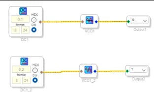
For the moment I just created the simplest schematics in order to test the hardware, like this:
I follow the document SigmaStudioHelp.pdf to see the procedures.
I have no issue to create the schematics, compile and download it. I put or dont't put the E2PROM (I don't see any difference)
When I connect an oscilloscope on the outputs there is nothing !!
Does the device automatically start after the downloading ? Or should we do a particular procedure to start it ?
Should we add the E2PROM when we want to simulate using SigmaStudio?
These trivial questions are not indicated anyware or they are somewhere but in what document ?
It seems we don't have the "All what you want to know on XXX but you didn't dare to ask"
For people accustomed to using it's trivial but not for beginners.
Is there somebody able to help me? If so, he will receive my greatest gratitude !!!
Yours faithfully,
Patrice
Audio Signal Processors
SigmaDSP Release 4.7
adau1451
software
SigmaDSP Audio Processors
Show More
Hello Patrice,
I fully understand your frustration and confusion. It is really easy but there are a lot of places where you can get hung up.
I created a YouTube channel last year. I have some play lists. This is the one for the ADAU1452:
ADAU1452/1467 Tutorial Series - YouTubeADAU1452/1467 Tutorial Series - YouTube
You are feeding the VCO with a very low level DC voltage so it is putting out a VERY low frequency signal. There are some Wiki help files and there is one for the VCO.
Voltage Controlled Oscillator [Analog Devices Wiki]
I suggest you start with the YouTube tutorials and you will be an expert before you know it!!
Have fun!!
Dave T
Hi,
Many thanks.
I hope I can progress...
Generally, an important file is missing to start: "MyFirstProgram"
Thanks to it , we can test the hardware and create our first program based on this file.
Best regards,
Patrice
Hi,
There is still a big problem.
The ADAU1452 is not similar to the ADAU1701, there are no analog outputs. Rather we use a DS42448 circuit outside the DSP and we use the TDM interface to control the outputs.
The board vendor doesn't indicate the way to do that. For him this is "trivial" and this is outside the support package.
1) the TDM interface should be configured: where could we find some exemples ?
2) How could we use the TDM interface ? : is there some exemple ?
For the moment I have absolutly no idea about the way to do so.
Is there somebody who can help me ?
Best regards,
Patrice
Hello patrice,
Saintot said:
The ADAU1452 is not similar to the ADAU1701, there are no analog outputs
Yes, you have to use the converters (ADC/DAC) externally. There are no on-chip converters in sigma3xx processors.
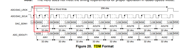
It seems like you are using CS42448 CODEC, and it has 6 ADCs and 8 DACs. I think you want to send TDM8 out of the DSP to your CODEC. The COEDC does accept TDM8 inputs.
Saintot said:
the TDM interface should be configured:
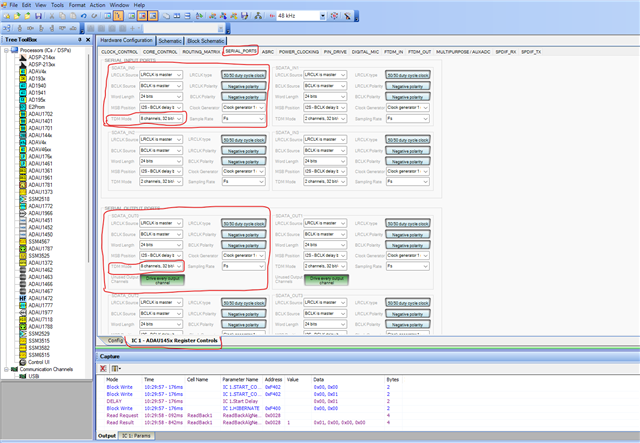
This is where you configure TDM in the registers, I configured input port 0 and output port 0 as TDM8.
If you take a scope and probe the BCLK_OUT0, LRCLK_OUT0 and SDATA_OUT0 then you will see 8 channels coming out.
For TDM8 input (to CODEC), you have to connect the data pin of serial output port 0 to DAC_SDIN1, BCLK_OUT0 to DAC_SCLK, LRCLK_OUT0 to DAC_LRCLK, and GND connections between the DSP and the codec.
It seems the codec will only be a serial clock slave in TDM mode, so the DSP should be the master.
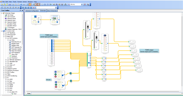
I will attach a project for TDM8 input and output.
TDM8_IN_OUT_Master.dspproj
In the project, I configured the serial port 0 for TDM in and out but I don't know which serial port you are planning to use, and which port headers are available in your hardware.
we would like to look at your hardware schematics to give you the best support.
Here are the few questions,
what is your sample rate?
where is the MCLK_IN to the CODEC coming from? Are you using the DSP's CLKOUT pin?
what about the inputs to the DSP (ADC's output)? How many channels you want to bring in?
Regards,
Harish
Hi,
Thank you very much for your quick answer.
Yes it is exactly what I wanted. Nice.
The vendor said "the AS42488 is in TDM mode" , I guess your explanation is correct.
Let me use it ...
Best regards
Patrice
Hi,
I looked at the schematics: the master clock (CLK_IN) is 12.288MHz and both clocks (CLK_IN and CLK_OUT) are sent to the CS42488.
The guy who sold me the board promised to send me more details ... I cross my fingers
BR
Patrice
Hi,
The board is working fine with the Hardware configuration you gave me.
I can see a sine wave of 2kHz with amplitude +/- 2.3V , it correspond to a sine wave generated with -9dB.
What is the reference amplitude in fact ?
Of course it is not possible to generate a 0dB sine wave (because there is saturation in this case).
Best regards,
Patrice
Hi,
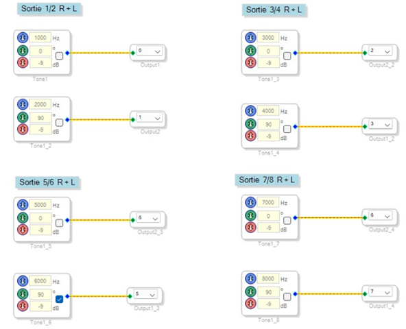
I created this test of outputs:
I can see that for outputs 1/2 and 3/4 this is ok.
For outputs 5/6 and 7/8 the frequency is correct but the amplitude is not good.
For exemple intead of a sine curve I see a square curve at the correct frequncy 5kHz
I can change the level in the box of the sine synsethiser that does not change anything.
It seems the data format is not correct.
What is the meaning of SDATA_Out1 to SDATA_Out2 ?
Do we use only the first ?
BR,
Patrice
Hello Patrice,
Saintot said:
What is the reference amplitude in fact ?
Below is what I found in your codec's datasheet.
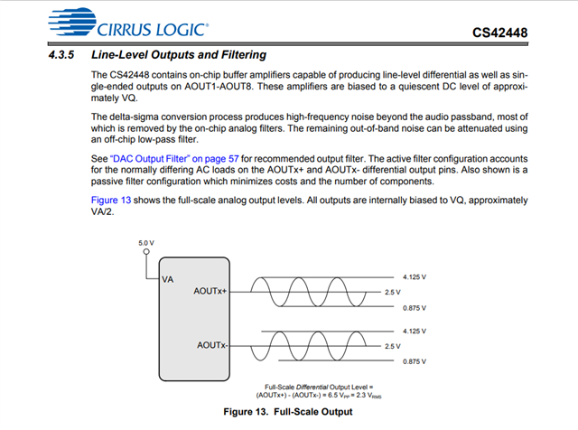
A full-scale signal will produce a 4.125V during a positive peak and 0.875V during a negative peak. The pins are biased to quiescent DC level named as VQ, where VQ = VA/2 = 5/2 = 2.5V. The analog output pins will go above 2.5V for a positive cycle and below 2.5V for a negative cycle.
Saintot said:
Of course it is not possible to generate a 0dB sine wave (because there is saturation in this case).
The internal oscillator blocks in the SigmaDSP cores produce a 24-bit 0dBFS sine wave. So, you can generate a 0dBFS signal for a 24-bit audio.
Saintot said:
It seems the data format is not correct.
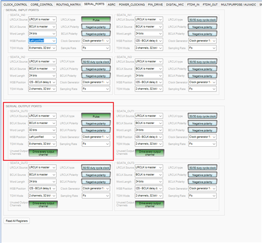
I just noticed that, the CS42448 by default operates with a frame sync in pulse mode and the MSB position as left-justified.
By default, the ADAU1452 operates with an LR clock in 50/50 duty cycle mode and the MSB position in one-bit delay mode (I²S). So, please try changing the settings like shown below.
Saintot said:
For exemple intead of a sine curve I see a square curve at the correct frequncy 5kHz
It would be great if you can send us the scope shot of the waveform and your hardware schematics.
Saintot said:
I can change the level in the box of the sine synsethiser that does not change anything.
I can see that some of the boxes are unchecked which means it's muted. Make sure that you enabled the tone module and the USBi communication is working properly, these changes are in runtime, so if you have a problem with USBi communication then the changes will not be updated to the DSP.
Saintot said:
What is the meaning of SDATA_Out1 to SDATA_Out2 ?
Sigma3xx DSPs have four serial input ports and four serial output ports. The input and output serial ports are independent. Input/output Port 0 and 1 support up to 16 channels and port 2 and 3 support up to 8 channels. For more details, refer the datasheet.
Each input/output ports have three pins.
For serial input port 0, the pins are named as BCLK_IN 0, LRCLK_IN 0, SDATA_IN 0.
For serial input port 1, BCLK_IN 1, LRCLK_IN 1, SDATA_IN 1. The same goes for serial input port 2,3.
For serial output port 0, it's BCLK_OUT 0, LRCLK_OUT 0, SDATA_OUT 0. The same goes for serial output port 1,2,3.
Saintot said:
What is the meaning of SDATA_Out1 to SDATA_Out2 ?
Do we use only the first ?
SDATA_OUT 1 is the data pin of output port 1 and SDATA_OUT 2 is the data pin of output port 2.
If you are using TDM8 then you can use any one of the four serial output ports. it's totally depending on your hardware design. All four ports can do this work without a problem. It's totally depending on your hardware connections and respective port configurations.
since you didn't attach your hardware schematic, I don't know which port you are using, so I generally configured for output port 0.
Kindly share your hardware and sigma studio schematic, so that we can be specific.
If still have a problem with analog waveform, please attach the scope shot of what you are getting.
Regards,
Harish
Please log in to reply.