Anti Noise Setup for machines (ANC) with EVAL-ADAU1467Z, problems with broadband recordings
Hello Forum,
we are using an ADAU1467 Evaluation Board to build an ANC setup in an anechoic chamber (for testing purposes). We are using big JBL Boxes and play back a broadband recording of a machine.
Aim is to attenuate a certain frequency at the point of the error microphone (e.g. 200Hz). Special constraint is, that we don't have a dedicated reference microphone to capture the noise, but we bandpassfilter the errorsignal in order to get the reference signal. Furthermore the noise we play back is from a machine which can drive through various patterns with different RPMs (Revolutions per minute). The setup should work for all patterns. The RPM stay constant for minutes, but also can sweep from low to high and vic versa.
We are using the Modified FX LMS algorithm where one can train the secondary path beforehand.
We found a tap size and alpha setting where the attenuation is really good for a constant RPM of the machine and we get an attenuation of 15dB.
But as soon as we ramp up the RPM, the setup doesn't work anymore and we get much less or none attenuation at all.
Isn't that something the Modified FX LMS algorithm could handle?
Further question, when introducing a delay in there reference signal path, should the filter converge anyway, regardless of the delay? The noise has sinusoidal parts in it.
What we found out is, that putting an delay there quickly reduces the attenuation.
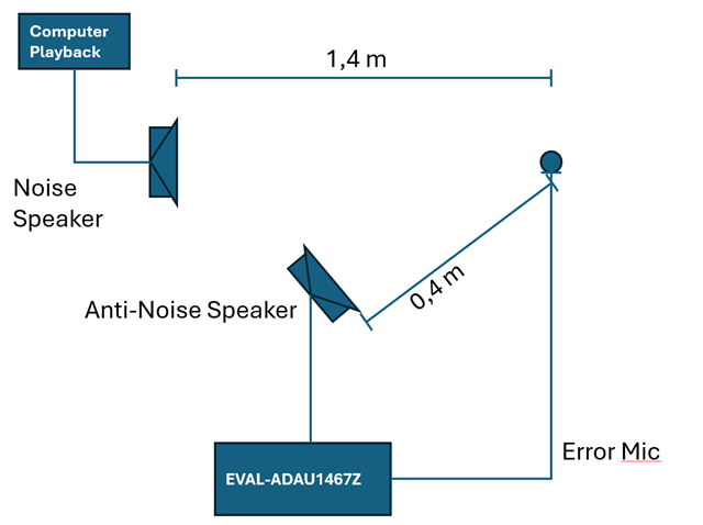
As you can see below the distances are quite big. Furthermore we are using a sampling frequency of 48kHz.
Edit Notes
Added schematic, changed subject title
[edited by: Kol2425 at 11:31 AM (GMT -5) on 10 Feb 2025]
Audio Signal Processors
anc
ADAU1467 Evaluation board
hardware
adaptive filtering
anti noise
SigmaDSP Audio Processors
ModFXLMS
anc projects
Show More
Hello Kol2425,
With noise cancellation delay is usually your enemy. I see from your diagram you have 1 meter if difference of travel from the noise source to the error mic and noise cancellation source to the error mic.
By my rough calculations. 1meter is 2.9ms. So the anti-noise is arriving 2.9ms early. This is NOT taking into account any delays in the signal processing and the computer outputs and the DSP outputs etc. Lots more goes into this of course.
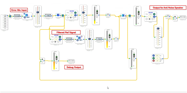
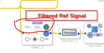
At 48kHz you are adding 2,000 samples which is ~42ms. This means your anti-noise signal is arriving far too late. Take a closer look at your timing between the two signals. You need to develop the anti-noise signal before at least 2.9ms before the speaker emits it out into the room and your anti-noise signal is emitted into the room to arrive exactly in time.
You will also need to understand the latency of all the converters and processing along the way. It can get a little difficult.
Dave T
Hi Dave,
thank you! Regarding the 2,000 samples you are refering to, that is the processing delay on board right? How do you come up with this number, is there a table available which tells me that block xy adds z delay to the algorithm? That would be great!
Because ~40ms is roughly the exact delay, but i measured it via an acoustic impulse.
Hello Kol2425,
Here is where I got it from:
I figure you will have to delay it by less than 139 samples. 139 samples is 1 meter. But, you have other delays involved with the converters and the DSP processing. So this will need a little adjustment from my viewpoint.
It is great that you used an acoustic impulse. I guess in the end that would include all the other delays that can get challenging to calculate.
Dave T
Hi Dave,
the current delay was set to 0, so that was not the issue. But we deleted them nevertheless. What causes a huge delay are the FIR Filter, replacing them with biquad IIR filter reduced the delay by nearly 30ms.
Still we need to get faster and we figured that using a 96kHz or 192kHz sampling rate could bring us step forward.
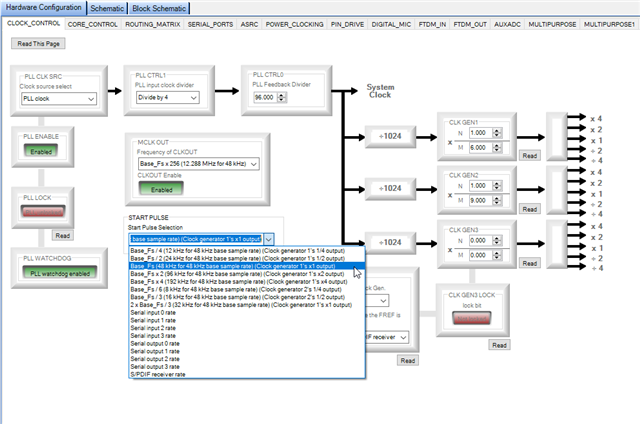
I know the crucial part is to get the correct sampling frequency in the hardware config, but i could not figure out how to do it exactly.
Do i need to change the start pulse or the CLK GEN1 ratio, or both? Do i need to change somethings else in the config, e.g. serial ports?
Thanks for your help!
Hello Kol2425,
Unless there are some extenuating circumstances I prefer to keep it simple when it comes to setting the sample rate.
Usually people will use a 12.288MHz crystal to drive the PLL. So set up the PLL for the default "base" rate of 48kHz which is the 256xfs setting for the PLL. Then the clock tree built into the part gives you options up and down from there. If you were to setup the base rate to be 192kHz instead of 48kHz, then the clock tree would have a base rate x 4 rate flying around in the part. That is a 768kHz sampling rate. This is too fast and will just eat up power for no reason! So it is best to set it up for 48kHz base rate and then set the start pulse to the "Times-4" "X-4" setting and you will get 192kHz.
Then for the clock generators that drive the serial ports the same thing applies. Leave Clock-Gen1 set to an N/M of "1/6" and you will get the multiplied and divided outputs available via register settings.
So you can choose the "X-4" output of clock gen1 and get 192kHz sampling rate.
There is no reason to set the X-1 setting to be 192kHz.
Now this all said, it will be difficult to run a serial port at 192kHz sampling rate. If you are using Stereo I2S then it is easier but any TDM format becomes difficult. You will have to adjust things like drive strengths and I strongly recommend you have the clock direction be the same as the serial data direction. So the serial input ports of the DSP should be a clock slave and the serial output ports of the DSP be a clock master. This gives you the best timing margin for the data to be stable and correctly transmitted. This is a longer discussion and I have discussed this in many posts over the years. This is nothing to do with limitations of the parts and everything to do with physics and the pesky thing called time!
You were very correct to use IIR filters instead of FIR filters. If you are using converters and have any choices for oversampling then the less oversampling the better. Those are usually FIR filters and if it is 64x over sampling then you have 64 samples of latency. With things like PDM mics you have choices of how you operate them. With some DACs you might have choices. I wish the good old R2R ladder DACs were still around and available.
Thanks,
Dave T

Hello,
You can use the MFxLMS filter for this. Note your block diagram should show the signal that goes to the noise speaker should also go to the DSP. That is the reference signal for the LMS. You show 1.4 - 0.4 = 1 meter of distance between the primary and secondary paths. As Dave said that's approx 3 msec or 144 samples. The latency through the eval board codec etc. is less than that so the system should be causal.
See attached project. There are instructions in the schematic to get it running.
ANC MFxLMS.dspproj
Hi guys,
DaveThib thanks, the change of the sample rate did work!
bitmechanic Nice, i will have a look at the project.
In the meantime i did make some changes to the original schematic from above and i get some decent results:
- feed in (an estimation of) the noise signal as a reference into the board. That is your suggestion from yesterday bitmechanic aswell and that is the classic approach. Previously we couldn't get hold of an noise signal estimation so we tried out to generate it from the error signal, there is some literature about feedbackward ANC projects. But it is not easy. Anyway having the original noise signal is always better i think.
- use IIR filters and change the sampling rate
- i got the biggest improvements in turning of the bandpass filter in the reference channel. Maybe the algorithm works only if the error and reference signals are coherent in terms of spectral information (bandwidth)?
Anyway i get an attenuation of 10dB and i am quite happy about it. But i will definitely try out your project bitmechanic .
Please log in to reply.