MCLK Source Select on ADAU1467 eval board
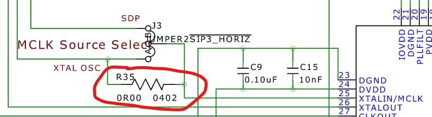
Whilst reviewing the schematic for the EVAL-ADAU1467 board, I've noticed an 0R00 resistor (R35) that continuously connects the crystal to the XTALIN/MCLK pin of the ADAU1467 DSP. Does this not compromise using an external Master Clock when setting the jumper J3 to position B (connect an external MCLK source to the input of the DSP)?
is this 0R00 resistor, and trace, required?
Thank you.
Mark
Audio Signal Processors
Datasheet/Specs
mclk
adau1467
EVAL-ADAU1467Z
SigmaDSP Audio Processors
EVAL-ADAU1467
SigmaDSP
Show More
Hello Mark,
Yes, you are correct that until you remove that resistor R35, Crystal can be the only MCLK source which is mostly preferred. But if you wish to provide MCLK from an external source, then you can remove that resistor and put the jumpers on in B position of J3.
If you want to use the crystal again, then put the jumpers on in A position of J3.
So, removing that resistor gives you an option that you can utilize with two jumper positions.
Hope this helps.
Regards,
Harish
Thanks, Harish. So was there a reason for R35 being there in the first place? How does it still work on the Eval board if someone is using with the jumpers in position B?
Hello Mark,
Sorry, I wasn't clear with my previous reply.
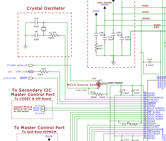
That jumper and resistor give you options for MCLK source for the DSP.
Initially, when the resistor is in place, the only MCLK source to the DSP is the on-board crystal oscillator. Most people want to run the DSP off from its own crystal. So, by default the crystal is connected to the MCLK_IN pin of the DSP via a 0ohm resistor (and to header J3).
So, at any point of time, if you ever want to provide MCLK to the DSP from external sources like MCU, other processors etc. to maintain synchronization between two chips, then you remove the 0ohm resistor and directly give the MCLK to the center pin of the header J3.
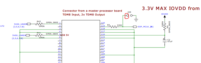
The jumper position B will be used, when you give the external MCLK to J20.
J20 is located next to the DIP switch S3.
You can either give your ext MCLK to the center pin of J3 (no need of jumper) or give ext MCLK to J20 and put the jumper in 'B' position of header J3.
If you want to use the crystal again then put the jumper in 'A' position.
Hope this clears things up.
Regards,
Harish
Thank you. This helps. I am designing a circuit that takes Dante into the SigmaDSP for processing and then sends it back out onto the Dante network. Since Dante requires use of it's own MCLK I want the DSP to run on this clock so I don't have to use the ASRC's (as there won't be enough channels if I do that). Will this work?
Many thanks.
Mark
Please log in to reply.