What is SPI mode CPOL CPHA for ADAU1701?
There seems to be quite a bit of confusion over ADAU1701 and SPI mode. What is it?!
This post seems to indicate it's SPI mode 0 (CPOL=0 CPHA=0), RE: ADAU1701 SPI mode
This says (not specifically about the ADUA1701) in general Analog's IC use SPI mode 3 (CPOL=1 CPHA=1) Which SPI Mode is used by SigmaDSP Devices?
The datasheet is really not that clear.
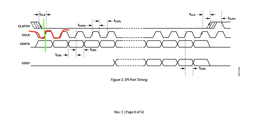
The default clock polarity is high on the left-hand side and low on the right-hand side, so CPOL is not clear. However, it indicates that the data undergoes a change on the falling edge and a reading on the rising edge. So I guess this value is consistent with SPI mode 3 (CPOL=1 CPHA=1)
Audio Signal Processors
Datasheet/Specs
spi
SigmaDSP Audio Processors
adau1701
Hello djfexlabs,
The timing diagram does show that the falling edge of the clock is the data-change edge and that the clock rising edge is the data sample edge.
I agree there has been some confusion. Our eval boards for this part pretty much all use I2C except for our internal bench eval board. Plus, I think all 3rd party boards I have seen are also all using I2C. It frees up the WB and WP pins for that functionality if desired.
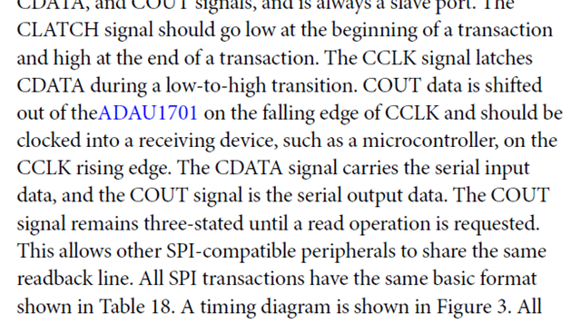
The text in the datasheet also detail this:
Dave T
Hi Dave,
Thanks for the reply and all the other helpful comments on the site!
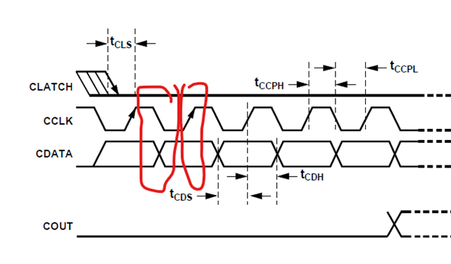
OK, so if the data should be read by the IC (i.e. data is latched) on the low-to-high transition. Then this could be:
SPI mode 0 (CPOL=0 CPHA=0)
SPI mode 3 (CPOL=1 CPH=1)
So can the device support either mode?
If you look at the left-hand side of the diagram, it seems to indicate the idle clock state is high, so this would mean CPHA=1 or SPI mode 3.
Or you could conclude SPI mode 0 by looking at the right-hand side of the diagram (not shown in the screenshot above).
(SPI mode 3 is working in my code.)
Hello djfexlabs,
If you look down into the SPI section of the datasheet it actually shows it. The timing diagrams are there just to show certain timing measurements to help to understand what they are.
Have a look here. The clock should sit high when no transaction is happening. This fits with the clock transition to a low to change data and start a transaction. Of course I am not talking about the CLATCH. That behavior is obvious.
I makes sense that SPI Mode 3 would be working in your code.
Dave T

That is exactly what I was missing - thanks for the all the patient help
Please log in to reply.