Fault monitor on GPIO's.
Hello all,
Looking for some guidance on this project. I using a ADAU 1467, driving 5 amp chips and is part of A2B system. I want to send fault and warning flags from the amps and A2B network.
I want to > Read the fault, store the fault in MCU, and clear the fault.
An array of logic gates is the way that I am thinking now. But I am not sure. Are there any examples of this type?
thank you.
pf
Audio Signal Processors
a2b
software
adau1467
SigmaDSP Audio Processors
gpio
SigmaDSP
Show More
Hello pf,
Thank you for reaching out with your project details. To ensure we provide the most accurate guidance, we’d appreciate a few clarifications regarding your setup:
Fault Sources: Could you please specify the type of amplifier chips or A2B system you are using and how the fault/warning signals are exposed (e.g. GPIO pin)?
MCU Role: How is the MCU interfaced in your system?
Are you expecting the MCU to forward the fault information to the ADAU1467, or will 1467 be reading them directly from the amplifier chips or A2B system?
what do you expect the ADAU1467 should do? Is it like the ADAU1467 reading the fault flag from amp and mute the outputs of the DSP accordingly?
Once we have these details, we’ll be in a much better position to suggest a solution or point you to similar reference designs.
Regards,
Harish
ADAU1467 with multiple MP pins configured as GPIO inputs, directly receiving digital fault or warning signals from:
Amplifier chips from TI TAS6424RQDKQRQ1
A2B-related power supervisory circuits AD2428.
These fault lines are digital (e.g., active-high or active-low) and connected to dedicated MPx pins on the DSP with no debounce.
The MCU does not forward fault states to the ADAU1467.
Instead, ADAU1467 reads these fault states directly via GPIO MP pins.
The MCU may read back fault latch status from the DSP (e.g., via I²C or SPI) or trigger a reset of latched faults via a dedicated GPIO input.
The ADAU1467 monitors fault/warning lines.
When faults are detected, it should:
Latch the fault condition so it’s not missed by the host.
Optionally mute the signal path (e.g., DACs or internal mixer outputs) to protect hardware or signal integrity.
Faults should remain latched until explicitly cleared by the MCU, or reset switch.
MP5 = Input from pin. No debounce. MP function selected (SUB_FAULT)
• MP7 = Input from pin. No debounce. MP function selected (AMP_3V3_SW_FLT)
• MP10 = Input from pin. No debounce. MP function selected (SUB_AMP_WARN)
• MP12 = Output without pull-up (DSP_ALERT)
• MP14 = Input from pin. No debounce. MP function selected (AMP_10V6_SW_FLT)
• MP15 = Input from pin. No debounce. MP function selected (A2B_PWR_SW_FLT)
• MP16 = Input from pin. No debounce. MP function selected (SAT_AMP1_WARN)
• MP17 = Input from pin. No debounce. MP function selected (SAT_AMP2_ WARN)
• MP18 = Input from pin. No debounce. MP function selected (SAT_AMP3_ WARN)
• MP19 = Input from pin. No debounce. MP function selected (SAT_AMP4_ WARN)
• MP20 = Input from pin. No debounce. MP function selected (SAT_AMP1_FAULT)
• MP21 = Input from pin. No debounce. MP function selected (SAT_AMP2_FAULT)
• MP22 = Input from pin. No debounce. MP function selected (SAT_AMP3_FAULT)
• MP23 = Input from pin. No debounce. MP function selected (SAT_AMP4_FAULT)
Hello zazenaudio,
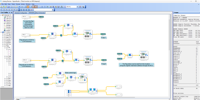
We have made a logic based on what we understood from your explanation. Please try this and let us know if this is what you are looking for.
we have quickly tested it here, it seems like working (what we designed/expected to work), so just test this and let us know.
Sorry, I have no time to explain it fully, comments are there in the schematic and it's just some basic logics.
Fault monitor on GPIO.dspproj
Hope this helps!
Regards,
Harish
Please log in to reply.