ADAU1701 filter theoretical gain curve vs measured oscilloscope output mismatch
Hello,
We are currently using ADAU1701 + SigmaStudio to design multi-stage IIR filters for hearing-loss compensation. During our experiments, we noticed that the measured output voltages on the oscilloscope do not fully match the theoretical gain curve shown in SigmaStudio or MATLAB.
Test setup:
Input signals:
Signal generator sine waves from 1 kHz to 6 kHz
Tested with 0.1 Vrms and also 1 Vpp (~0.35 Vrms) amplitudes
ADAU1701: sampling rate set to 16 kHz
Output: measured directly from DAC (AF OUT) with oscilloscope
Filters: 8-stage and 10-stage Yulewalk IIR filters, coefficients imported from MATLAB into SigmaStudio
Problem observed:
Theoretical filter curve (fvtool and dB calculations) shows e.g. +10 dB at 1 kHz and +30 dB at 3 kHz.
However, measured oscilloscope results differ: at 1 kHz the gain is larger than expected, while at 3 kHz the compensation seems smaller.
In addition, the bypass output (VIN routed directly to output) does not equal the signal generator input Vrms (for example, 100 mVrms input becomes ~43 mVrms at bypass).
Questions:
Why is there a mismatch between SigmaStudio/theoretical filter curves and real oscilloscope measurement?
When calculating dB gain (20·log(Vout/Vin)), should the reference be the signal generator input or the bypassed VIN from ADAU1701?
Does using higher filter orders (e.g., 8 vs 10 stages) introduce measurable error in amplitude compared to the simulated magnitude response?
Any insights or references (especially on proper measurement methods with ADAU1701) would be greatly appreciated.
Thanks in advance!
Audio Signal Processors
adau1701 usbi
hardware
sigmastudio
SigmaDSP Audio Processors
SigmaDSP
adau1701 sigmastudio
adau1701
Show More
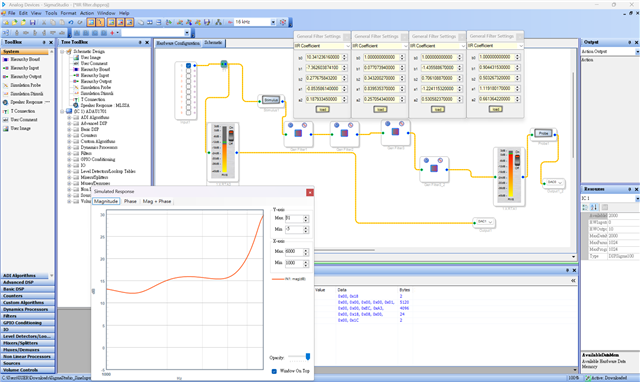
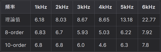
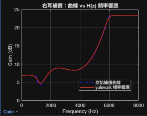
Sorry, it`s my first time posting a question on the site. Here are our experimental result.
SigmaStudio project setup with filter coefficients
Comparison of theoretical vs measured gains (table format)
MATLAB simulation: target vs Yulewalk filter response
Hello Jaychen1110,
Can you provide the rest of the details of how you have set the sampling rate?
What are the clocks coming into the part? MCLK and of course the clocks to the serial port if you are using the serial port.
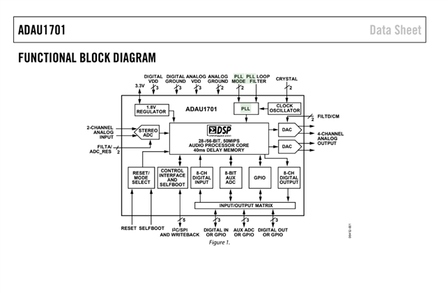
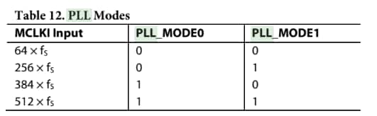
What are the settings for the PLL? This is done with hardware pins on this part.
Then the Program Length register setting?
The field up in SigmaStudio is only for SigmaStudio to know what the sampling rate will be so it can properly calculate the program parameters.
Dave T
Hello Dave,
Thanks for your reply. Here are the details of our current setup:
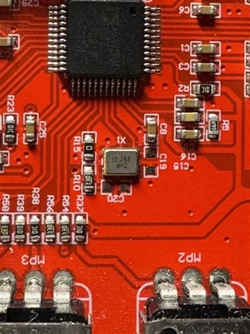
MCLK source: Our board uses a 12.288 MHz crystal oscillator connected to the MCLKI pin.
PLL settings:
PLL_MODE0 = [0 or 1, to be confirmed by measurement]
PLL_MODE1 = [0 or 1, to be confirmed by measurement]
→ This corresponds to [example: 0b01 → 256 × Fs] which means the actual sample rate is [example: 48 kHz].
p.s:I don't know are these PLL setting what you want? If not. please let me know. I will do more research to answer your question.
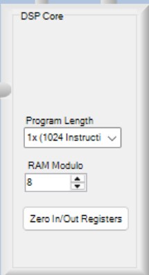
Program Length register: Set to the default 1024 instructions (as shown in SigmaStudio Register Control).
In SigmaStudio we had set the project to 16 kHz sampling rate, but based on the PLL_MODE pins it seems the actual sampling rate is [likely 48 kHz]. Could this mismatch explain why our measured oscilloscope results do not match the theoretical filter gain curve?
Thanks again for your support!
Best regards,
Jaychen
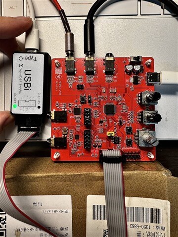
This is our ADAU1701
Please log in to reply.