Why the input signal voltage in SigmaStudio is different with bypass signal voltage
We use signal generator to input 300mVp-p(Peak to Peak on the oscilloscope), but when we measure the output of the ADAU1701(DAC1) it show that the voltage only has 160mVp-p even it's bypass. Why?
Audio Signal Processors
hardware
SigmaDS
sigmastudio
SigmaDSP Audio Processors
adau1701
Show More
Hello Jaychen1110,
Well, there are a lot of places and variables here and you gave me little to no information.
The ADC might not be setup externally to the DSP to produce a full scale digital signal that will produce the same voltage when this full scale signal is presented to the DAC.
You have many factors:
1) the analog buffers before the ADC input
2) The setup of the ADC gain
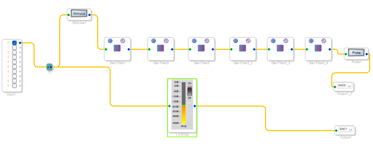
3) Then at this point you are in the digital domain. So as you said, even in bypass (you did not define what bypass means and your project only shows that one channel goes directly to a DAC output so I think that is what you mean?)
Even n bypass the DAC gain is not changeable.
4) then the analog output amplifier circuit might add or subtract gain.
Let me demonstrate:
First you will be going through some sort of OpAmp stage before the ADC which can add or subtract gain.
Then you have the setup of the ADC gain...
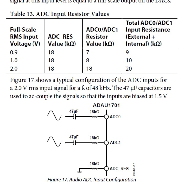
Here is the ADC gain setup as detailed in the datasheet:
The first listing is such that at 0.9Vrms signal will produce a 0dBFS signal. (Digital Full Scale)
The other two will not be the same level in the DSP core.
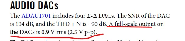
Now to the DAC details in the datasheet:
This means that a 0dBFS signal will produce a 0.9Vrms signal out of the DAC.
Then it will depend on the amplifiers after the DAC.
So if you have unity gain amps on both the input and the output and you have the ADC setup for 0.9VRMS then you should get the same output as you are putting in. There is always a slight change, it is never perfect but it will be close.
One thing I always do in my projects is to put in a MUX with the ability to select an oscillator inside the DSP core. This way you have a known 0dBFS signal inside the core that you can send to a DAC output. Then you can see what a full scale signal will produce.
Watch my Troubleshooting video on my YouTube channel.
How to use SigmaStudio for troubleshooting
Dave T
Please log in to reply.