ASRC Lock on ADAU1466
Subject: ADAU1466 ASRC0 will not maintain lock with XU316 I²S (24-bit/48 kHz)
Hi ADI team,
Setup
ADAU1466, self-boot from EEPROM verified
Source: XMOS XU316 USB→I²S from Windows, 24-bit/48 kHz
Project: Base FS, Pulse/Clk Gen, Sample Rate all 48 kHz
Control: SPI reads/writes
ASRC page screenshot attached
Issue
ASRC0 will not stay locked. SigmaStudio shows Unlocked for ASRC0 while ASRC1–3 show Locked.
Any compile while audio is playing flips the page to Locked, but after reset/power cycle it returns to Unlocked.
EEPROM writes and self-boot confirmed good.
Reading 0xF580, bit0 for ASRC0 consistently reads 1. I know 1=LOCKED from forum guidance, yet the UI shows Unlocked and the lock does not persist.
I cannot obtain a 0x0000 read for ASRC0 in any steady state, and long-term it won’t hold lock.
What I’ve tried
Changed Clock Generator parameters and sources.
Reworked the routing matrix for ASRC0 multiple ways.
Adjusted all serial-port input settings that feed ASRC0 (I²S mode, LRCLK polarity, BCLK edge, word length/slot mapping).
None of these yield a constant lock.
Requests
Confirm definitive ASRC lock polarity and whether the SigmaStudio ASRC page can report the inverse state on ADAU1466.
Provide a recommended boot/reacquire sequence when in=out=48 kHz (e.g., LRCLK drop timing, register sequence).
Advise additional diagnostics beyond 0xF580, e.g., which ratio/status registers to monitor and expected values.
Thanks,
Zac
Edit Notes
Removed Image
[edited by: Zbotnik at 4:41 PM (GMT -4) on 10 Oct 2025]
Audio Signal Processors
Datasheet/Specs
software
sigma studio 4.7
SigmaDSP Audio Processors
sigmastudio4.7
asrc
adau1466
Show More
Here are a few more screenshots of my settings.
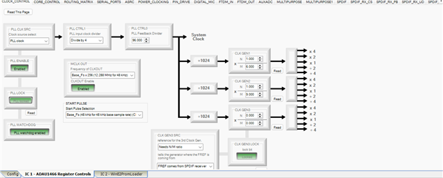
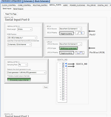
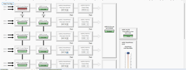
Hello Zbotnik,
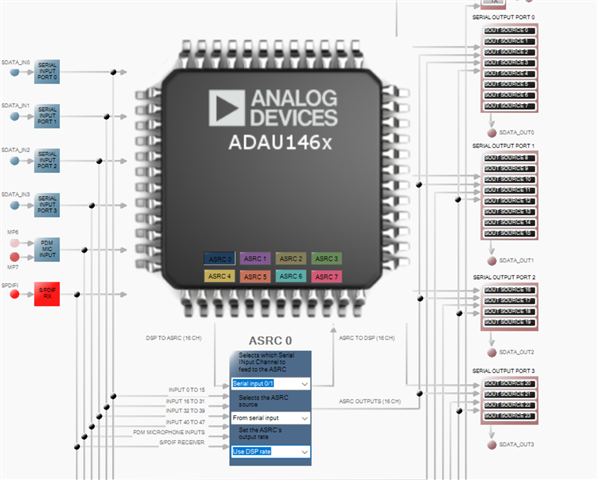
This is the page where you setup most of the settings for the ASRC.
You will see that I have it set to Serial port 0/1
Then From Serial Port
Then set the ASRC output rate to something that makes sense. It needs to be the rate of the core. The easiest is to select the USE DSP CORE RATE setting. This way if you change the core start pulse for some reason this will follow it.
Now, I am also assuming you are applying the LRCLK and BCLK to the serial port 0 clock input pins correct? You do have them correctly set to slave from clock domain 0 providing this is where you connected the clocks from the XMOS chip.
Dave T
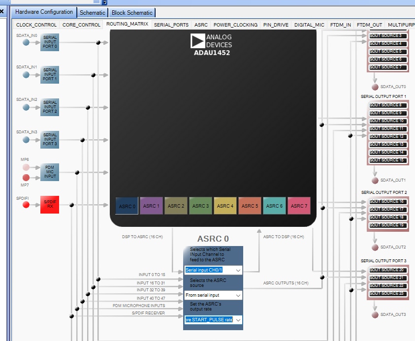
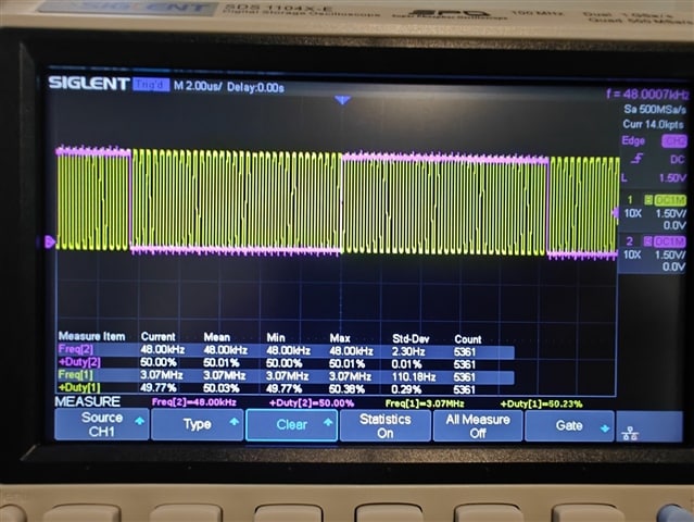
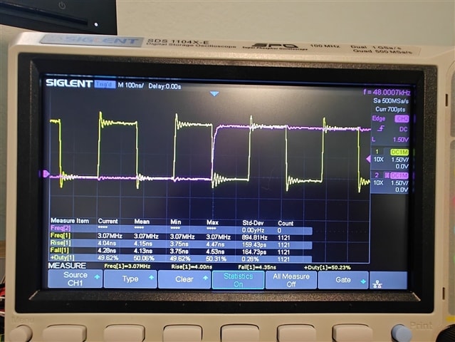
That is correct, I did grab the scope to check some stuff. It did in fact leave me more confused than before. On that note, nothing seems off, when I change the sampling rate and bit depth in windows i can see it jump from 48khz stable, all the way up to 384khz stable. That is on the output of the xu316. BCLK is sitting at a solid 3.07MHZ. I measured for some time, roughly 10 minutes. I had no noticeable deviations.
I then metered the LRCLK inputs on the ADAU1466 while being fed from the xu316. Same exact readings. I did assume that the 3 inch cables I'm using as jumpers were not the issue. That was correct.
I then set probes on LRCLK In and Out of the ADAU1466. Both clocks are stable at 48khz which is what I'm aiming for. I can get the ADAU1466 to change somewhat reliably on the output side. Though, this matters little to me in this case as I just want 48khz stable. I did notice the presumed drift as they are not asynchronous. At this point I have no reason to believe its the USB transport.
I even get ASRC errors when I make a clean projects with just inputs leading to outputs and also changing the input serial to be slave to BCLK and LCLK. No matter what I do it just says error in ASRC 0.
I am beginning to think that I just have a bad device but that doesn't really make sense as the music that comes out is almost always perfect. It has been hard to tell what the occassional popping is coming from (setting in Sigmastudio wise) as I am constantly changing things to try and find what is preventing the lock.
Here is my Routing Matrix configuration.
Here are my scope readings verifying stable 48khz in and out, and BCLK stable at 3.07mhz as well as the clock on the adau1466 stable at 12mhz.
Note:the 49MHz clock is from the xu316 and is not being used, unless I can divide it by 2 as I don't think the adau1466 can accept anything above 24MHz
Thanks,
Zachary
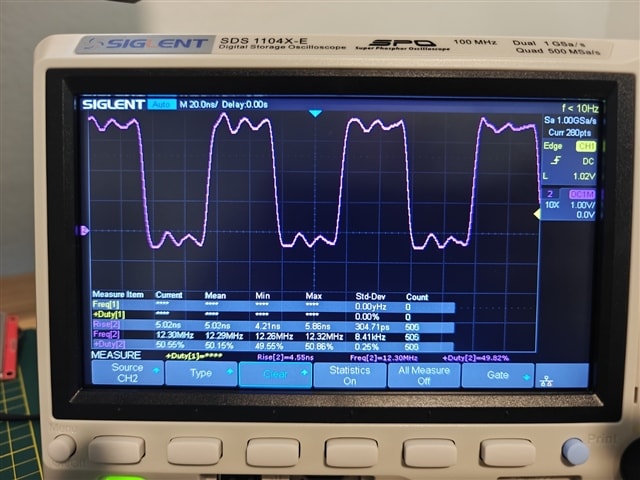
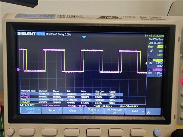
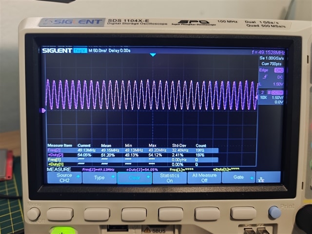
I am not sure if the Eeprom was the issue but I bypassed it with an ESP32 and left selfboot off to bypass the eeprom. I now boot from a ESP32 via SPI mode 3 and have a solid ASRC lock polling every 2 seconds on ASRC0 with the SAME configuration that would not lock after power cycle when using eeprom. I also use the same esp32 to control several encoders and LEDs. Neat.
Hello Zbotnik,
This tells me that the contents of the EEPROM must have some settings that are different? The EEPROM has absolutely nothing to do once the program is loaded and booted. It is connected to the master SPI port and once the selfboot program completes all activity stops unless your program is setup to save things to the EEPROM of course.
When you program the EEPROM you have to perform a fresh Link/compile/Download to update the program and the register settings etc., so that the contents of the EEPROM will be correct. If you had changed a register and did not recompile then the contents would be different.
That is the best explanation I give at the moment for something that seems illogical.
Dave T
ADAU1467 ASRC Lock Bits
Hi Dave,
Could you please take a look at this post and confirm whether a 0x0001 readout at address 0xF580 indicates that the ASRC is locked, and a 0x0000 readout at that same address means it is unlocked?
Also, can you verify that the datasheet(1466/62) appears to have these states reversed in that section?
Thank you,
Zac
Hello Zac,
I apologize for not commenting on the documentation in the datasheet.
There indeed is an issue with the documentation for the register 0xF580. The locked bits are listed backwards.
There is a little bit of internal organizational issues at play here. I found this issue many years ago. There were a lot of other issues with the datasheet that were either wrong or needed a lot more explanations and some additional specifications that were needed. These DSPs are automotive rated so if there are changes made to the datasheet it is a huge paperwork nightmare!! I had several automotive customers who needed changes made. So back in 2018 I made a HUGE amount of changes. Now, here comes the internal issues. I am in the consumer division and it is the consumer division who released the ADAU1452/51/50 but it was the automotive division that released the ADAU1467/66/63/62 so it is a different applications Engineer who is responsible for maintaining that datasheet.
My suggestions for you is to refer to the ADAU1452 Rev D datasheet that has all the changes made. Glance at the revision history on page 3 and you will see all the revisions I made back in 2018. One of them is page 154 which is the ASRC lock bit documentation.
All of these changes were never done to the ADAU1467/66/63/62 datasheet. Since these parts are so similar, the cores are the same, the registers are the same with only a few exceptions. The things like power dissipation and memory stats of course are different because of the extra memory and some changes to the serial port pins that are assignable. I still use only the ADAU1452 datasheet for things like the core and the ASRCs.
So again, I apologize that I neglected to pass this along to you. It has been a busy time for me.
Here is an example project where I test for ASRC lock and also check the ratio.
4276.ADAU1452 ASRC Lock Detect and Ratio Detect Example.dspproj
Dave T
Dave,
Thanks for flagging the 0xF580 documentation error. Confirmed: the lock bits are reversed in the ADAU146x datasheet. I’ll use the ADAU1452 Rev D datasheet going forward (pg. 154 for ASRC lock).
I spent a couple of days making an ESP32 act as a self-boot/program loader and a live parameter controller. After your note I verified the EEPROM path was fine and ASRC was locking correctly; the mis-documented bits were the root cause.
Current setup:
ESP32 on the SPI control port.
Four encoders driving Main, High, Mid, Low, and Sub volumes; phase invert; crossover enable/disable; reset; and lockout on all volume controls.
SigmaStudio logic for zero-latency audio-present detect and separate handlers for volume and encoder state changes.
MP7 LED tied to ASRC lock status.
MP6 LED blink patterns indicating input sample rate (.1hz, .5hz, 1hz and solid for 44.1/48/96/192khz sampling rate respectively).
Your example project for ASRC lock/ratio helped close the loop. If there are other known 146x erratum not mirrored from the 1452 Rev D doc, please point me to them. I can share my ESP32/SigmaStudio project files if useful.
Warm regards,
Zac
Hello Zac,
Great news and glad you are moving forward! I apologize for the issues. You ask about erratum. Have a look at page 3 of the ADAU1452 Rev-D datasheet where the revision history is listed. The revisions I added was a long list done in July of 2018. Most of these are simply expanding of details and adding some more info but a few are corrections. The PCB layout details and power supply regulator details are important. It was back in 2018 so it is tough for me to recall it all without looking at each item. The big differences in the parts (the Sigma300 verses the Sigma350) is the ability to assign serial data to expansion pins. The ASRCs were improved to not clip too early. Someone had found they clipped about 0.1dB early or something like that. Something really insignificant in my opinion. Then the SPDIF was improved for the clocking so it can operate up to 192kHz. Then to be able to split off the Master port I2C to GPIO pins so you can have both formats on the master port. Then of course the extra memory.
Dave T
Please log in to reply.