Query about PLL Lock in ADAU1761
Hello, we do use ADAU1761 in our module. The masterclock ADAU1761 MCLK is provided by a MPU , MCLK frequency is 26MHz. There are 2 power modes of the MPU (RUN and Low Power). The MCLK signal from MPU change a bit (rise + fall time + duty cycle) according to on going MPU mode but stays in the figures specified by the ADAU1761 datasheet (level of digital input). The issue is the following:
init in RUN MPU mode:
- We write R0 register to enable the core clock and select PLL clock
- We write R1 register to define the PLL dividers and enabling the PLL (PLLEN)
- We read R1 register, looking to lock bit and waiting lock bit = 1 (locked)
- The we can have access to registers above R1
Following the configuration the codec works.
then the MPU goes to Low Power mode for a certain duration, 26MHz signal is present during that phase and all power supplies as well (AVDD, etc..). During that period there is no access by SW to ADAU1761
then the MPU is back to run mode. So SW reads R1 register in order to check PLL lock bit, and unfortunately the lock bit is at 0, meaning PLL is unlocked and stay unlocked.
What are the potential reasons to get such behavior with PLL knowing the power supplies are still present and the MCLK as well ?
Thanks and regards.
Audio Signal Processors
hardware
SigmaDSP Audio Processors
adau1761
Hello philippe2026,
I think you are running into a problem I first noticed a few years ago but I do not know exactly why this seems to happen.
You mentioned an MCLK of 26Mhz, I assume this is actually 24.576MHz? It would be good to know your setting for the PLL to understand what the core rate is and therefore the sampling rate.
I am guessing that when you switch the MPU to low power mode there are some small discontinuities in the MCLK and that might be causing the PLL to unlock and then it is having an issue relocking.
Here is a post where we mentioned the issue with the PLL. Your symptoms are a little different. I originally found this when a customer complained that the PLL would only lock 1 out of 4 times the part is started. I was able to replicate it. Look at this post:
ADAU1761 PLL issues with MCLK 24.576mhz - Q&A - SigmaDSP Processors & SigmaStudio Dev. Tool - EngineerZone
This is another post that points out some other possible issues:
MCLK to ADAU1761 cannot be locked in Sigmastudio - Q&A - SigmaDSP Processors & SigmaStudio Dev. Tool - EngineerZone
Dave T
Hello Dave,
Thanks for answering.
We init the codec's PLL as following:
0x0E -> R0: PLL Clock, 1024xFs, core clock disable.
0x0659 04F5 1B01 -> R1 according to table 17 of datasheet (MCLK input=26MHz, PLL output=49.152MHz = 1024xFs)
We wait PLL lock by reading R1 (lock bit)
Then we write 0x0F -> R0 (core clock enable)
Regards.
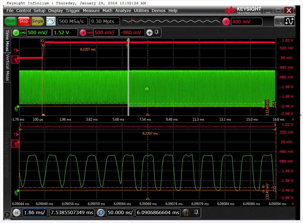
Hello Dave, there is quite no discoutinuities obsvered while going from run to lowpower mode and vice versa. only amplitude changes a bit but staying at acceptable level I think. exemple from low power to run. And if any it might be the case , why the PLL doesn't relock following this change ? thanks & regards.
Hello Phillipe2026,
Thanks for the last post. It was really helpful. I was in the process of thinking about your issue when you posted it. I see that you are using the PLL in fractional mode. Those settings seem correct. I was going to comment to see if you could change the frequency from the MPU but I understand that it is probably not possible due to the usual crystal frequencies driving an MCU and it is not easy to produce a fractional frequency from an MCU. Yes, it would be great to run the PLL in integer mode and use 12.288MHz MCLK frequency but thanks to your screenshot I think there are other things to chase first.
I am scratching my head a little about the voltage measurements on your scope screen. Negative numbers???
But, I will set that aside and carry on. I will assume the voltages listed are correct relative values. As in -2V is 2V from 0V.
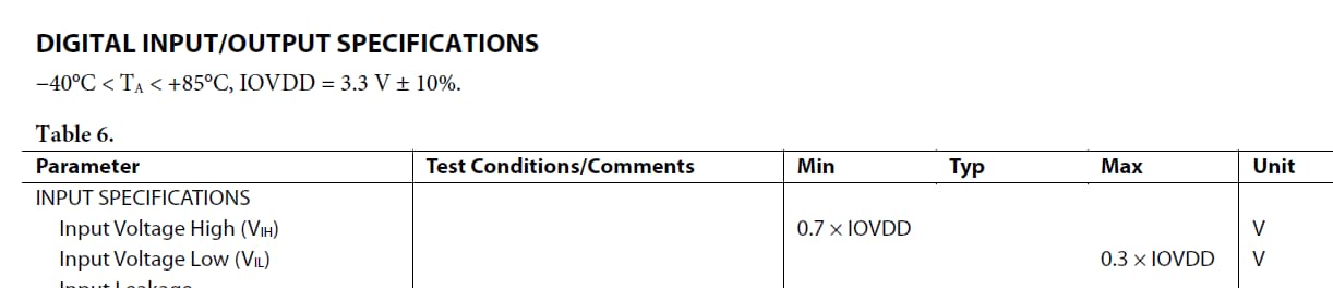
Here is the digital specs for the part:
So assuming you are using 3.3V for IOVDD. For the part to "see" a high signal it needs to be 0.7xIOVDD which is 2.31V
Then for the part to "see" a low the signal has to be 0.3xIOVDD which is 0.99V.
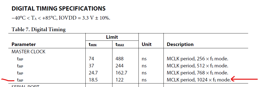
Then I also want to point out the timing specifications
this means in the mode you are operating in the minimum time for the MCLK frequency is 18.5ns and the longest time is 122ns.
26MHz has a period of 38.46ns. So you are fine with that specification.
What I am not happy about is that the datasheet does not specify the high or low time for the MCLK input!
I am going to make an assumption that it will be similar to the serial port timing. The BCLK and LRCLK pulse width low or high is 5ns.
With all this in mind there are some issues that concern me with your screenshot of the MCLK.
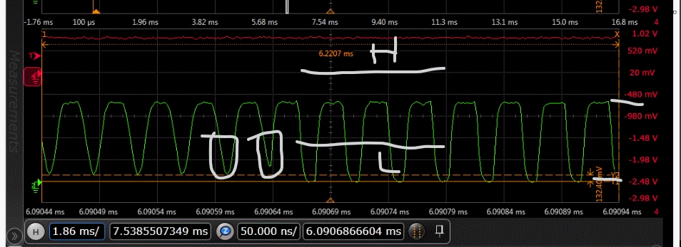
First, the voltage of the waveform from high to low is only around 2V. Which means if the voltage is starting at 0V then it will never reach the 2.31V to register as a high!!
If it is starting at 3.3V then it will never get to the 0.99V level for a low!
I marked up your screenshot below to demonstrate these things.
In addition, I circled two low points which are VERY short and do not go very low. I am guessing these lows are not being registered as a low so the frequency would suddenly jump!!
This waveform is not very good. I suspect you have a lot of capacitance on the clock lines? Or is the drive strength of the MCU setup to be weak and there is a strong pull-up?
The good news is that I do not see a lot of reflections in the signal.
So I think you should look more carefully at the IOVDD voltage and then the waveform and the high and low timing to get it closer to 50/50 when taking into account what the V-hi and V-lo is.
I think you will meet the 5ns being high or low once you fix the voltage levels but the voltage levels may be the issue to cause the MCLK to more be properly "seen" by the PLL.
Dave T
Hi Dave,
Thanks for your deep analyis and comment. In fact IOVDD=1.8V in our design and codec IOVDD pin is connected to it. The part you highlighted is a digital zoom of the scope, so the voltage scale in red on right side is no relative to it but to the red signal only ( part without zoom on top of the display). Sorry for difficulty to read it . Anyway the signal forms are complying with the 0.3 IOVDD and 0.7 IOVDD of a CMOS input, please look here:
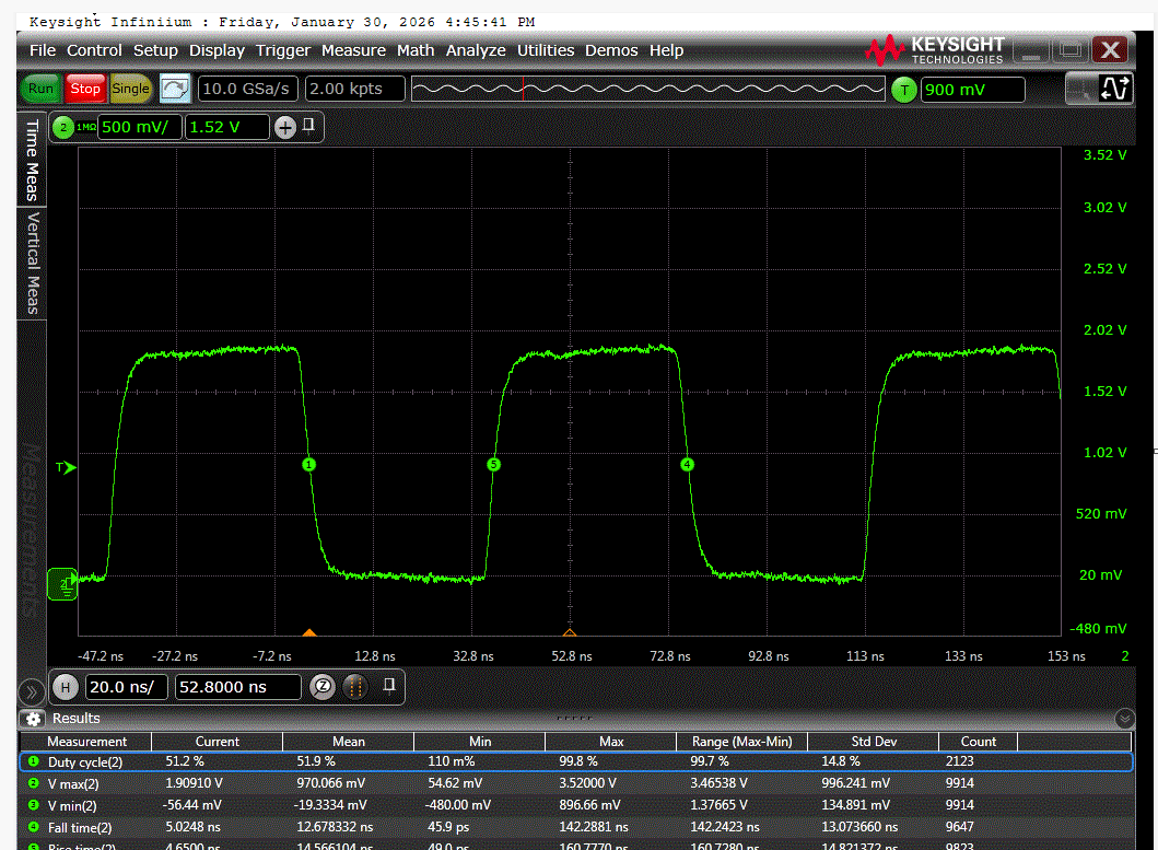
Here you can see the signal form during run mode:
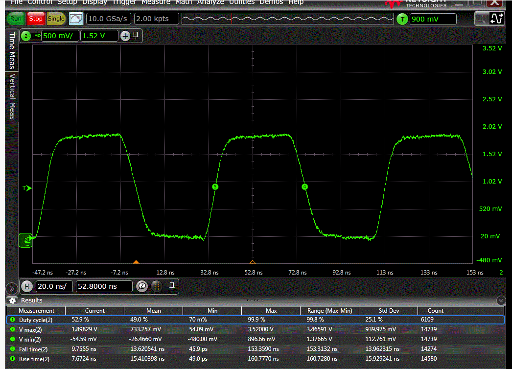
Here you can see the signal durig low power mode:
We have in both cases (more marked in low power mode due to MPU driver I guess with a lower duty cycle in particular) quite smooth edges. This is due to the fact we decided to adapt in serial the PCB line with a resistor, because without it was with faster edges for sure but with a lot of undershoot and overshoot and such noise could be seen in other sensible part of the module. We can tune the drive strenght (current capacity) of the MPU signal (MCLK), for the moment it has been set at minimum. Without the serial adaptation, we have add the same issue, I mean the PLL found unlocked.
Regarding the part of signal you highlight with circle, this is just at the moment where the MPU comes back from low power for going to run mode.
Please note if we stay in run mode, so with the 1st signal form, the PLL is never found unlocked. So I guess the levels and edges are correct. What is sounding strange to me is the following: pll locked during run mode, pll might unlocking during low power mode or during transitions between both modes, but why pll doesn't relock when the system is back to run mode ? The only way to re-lock is to rewrite R0 & R1 registers and then we reconfigure all others codec registers.
I will try with higher drive strenght so shorter edges.
Thanks for further comments.
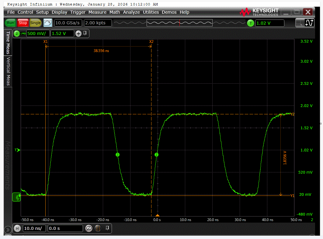
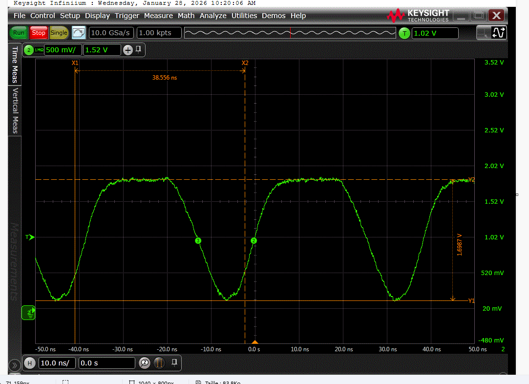
Hi Dave,
Rise & Fall times during run mode are about 4.1ns 4.5ns, including about 0.7ns from scope itself (500MHz)
Rise & Fall times during low power mode are about 7.6ns 9ns , including about 0.7ns from scope itself (500MHz)
Thanks
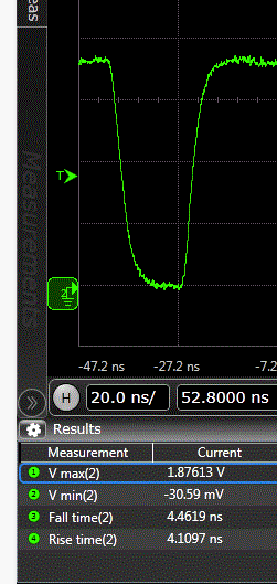
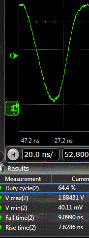
Hi Dave,
We performed the test with a 13MHz instead of 26MHz. We still see the issue with PLL found unlocked whenj back tu run mode following a low power mode.
run masterclock
lowpower masterclock
In both cases, I would say signals are compliant with datasheet specif including logical levels and duration of state 0 and state 1.
Any comments or suggestions from you side ?
Thanks.
Hello philippe2026,
Thanks for the additional info. Sorry that this continues to be difficult.
FYI, earlier when I was concerned about the logic levels and timing, you kept mentioning rise and fall times. While that is part of it, what I was looking for and focusing on was the length of time the signal is above the low-high threshold of 0.7V x IOVDD and below the high to low threshold of 0.3V x IOVDD. Those needed to be at least 5ns and from your new screenshots I can see they are so that is not the problem here.
I think we are running into a design issue with the PLL. This was an early design of a fully digital PLL with no loop filter required. So I am thinking the sudden slight change is enough to lock up the PLL such that it does not recover. So I would like to see if you could try a couple of things.
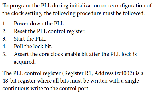
The first is easier. Follow what the datasheet suggests when making changes. So after you come out of low power mode, do this:
However, step one says to power down the PLL, well, there is no bit to do that! I think it is referring to the PLL Enable bit.
Also, disable the core clock.
Then follow step 2-5 and see if you see the lock bit
If this does not work then...
The second thing to try is see if there is any way in your system that you could generate a 12.288MHz MCLK signal? This is 256 x fs. Then use the PLL in integer mode not fractional mode. This may help.
Dave T
Hello Dave,
Thanks for answering.
Your 1st step was done without sucess. Then it is not possible to set frequency at 12.288MHz because in low power mode the MPU can deliver only 26MHz or fraction of it like 13MHz to ADAU1761.
Nevertheless we are focusing on potential sw issue on our side with may be an unexpected I2C access to ADAU1761 register. In such idea frame, we woud like to know if there are existing erratas on ADAU1761 I2C bus access like the need to add potential delay between successive I2C writings or if all works like writen in ADAU1761 datasheet.
Thanks for understanding and sorry for the delay of my answer versus your previous message.
Hello philippe2026,
There is no errata that I am aware of.
The only issue I have seen was with using 24.576MHz into the PLL would sometimes not lock.
Which is why I asked about using 12.288MHz instead. The other little thing that I would have asked for if I had been on the design team is that there is no reset pin and not even a reset register!!! A reset register would be handy. If you sense and issue, reset and start over! However, with this part you would have to gate ALL the power and signals going to the part and that is just not practical.
I still think it is a small glitch in the MCLK that is causing the PLL to malfunction. However, how to recover is a good question. I suggest you stop the MCLK. reset the PLL by disabling it. and possibly also stopping the internal clock and then starting it all back up. Supply the MCLK, enable the PLL then when locked enable the internal clock.
See if that helps.
Dave T
Hello Dave,
We found and correct issues in our SW design regarding the I2C access to audio codec. In term of power saving, we decided as well to shutdown the power supply of the codec during low power mode and to use a 2.048MHz masterclock without the use of PLL codec in run mode. So the codec is fully reinitialized when system goes from low power mode to run mode. It works now.
I really appreciate your dedication to our issue. Thanks for your advices and support.
Please log in to reply.