TDM2 oder 8 channels
Hey together,
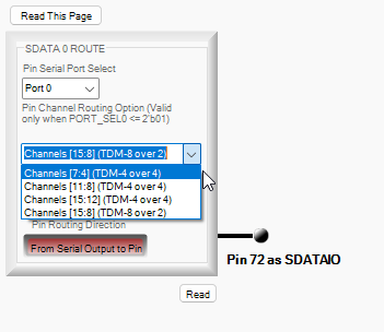
one question. We know that it is possible to send 16 channels of audio via serial port 0/1 via a single SDATA pin (16 channels), via 2 SDATA pins (2x8channels) and 4 SDATA pins (4x4channels). But we don't find the option to send it via 8 SDATA pins (8x2channels). Is this not possible in the ADAU1467?
We only have serial out 1 free and we have 2 DACs (1x 8 channel, 1x 2 channel). We would like to send 10 channels in total. We could configure that we send 3x4 channels (12 channel) but the 2 channel DAC accepts only 3.072MHz BCLK max. Which would not work in this setup.
Best regards,
Eric
Audio Signal Processors
hardware
adau1467
SigmaDSP Audio Processors
tdm
Serial Out
SigmaStudio v4.7
Show More
Hello Eric,
You can configure those 8 SDATAIOx pins to carry stereo signal. I have attached a project below which is configured for 4 stereo inputs and 4 stereo outputs by using SDATAIO pins, and 4 stereo inputs and 4 stereo outputs by using primary pin of each input and output serial port. Hence this project utilizes 8 stereo inputs and 8 stereo outputs.
You can refer the configuration and register settings in the project; I also added comments in the schematic.
0537.4IN and 4OUT I2S with SDATAIOx pins copy.dspproj
EricSa said:
We only have serial out 1 free and we have 2 DACs (1x 8 channel, 1x 2 channel). We would like to send 10 channels in total. We could configure that we send 3x4 channels (12 channel) but the 2 channel DAC accepts only 3.072MHz BCLK max. Which would not work in this setup.
The SDATAIO pin must be configured to one of the serial ports, so that the SDATAIO pin uses that port's clocks.
How many SDATAIO pins you have? and how many ports use SDATAIO pins?
EricSa said:
We only have serial out 1 free
Did you use all slots of other serial ports? Does serial port 1 have all 16 slots available?
I guess you set the serial output port as clock master, is that right?
Does any of your port run at I2S mode (3.072MHz BCLK)?
If you could tell me all serial output port configuration (in what mode, how many SDATAIO pins are utilized), channel usage etc, I will see if there is a way.
I just need more details about your setup.
Regards,
Harish
Hello Harishgowtham ,
thanks for your fast reply. I have checked your project, thanks a lot for it. I guess it will not help in our case but i will list all serial-ports maybe you have an idea.
Serial-Ins:
All blocked completly.
Serial-Outs:
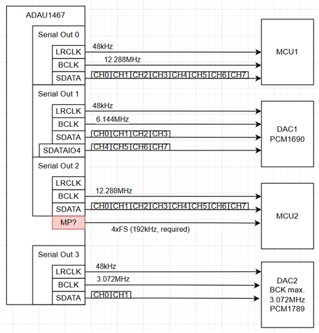
Serial-Out-0 (Runs as Master, TDM8, all 8 channels are send to an host MCU1)
Serial-Out-1 (Runs as Master, 2xTDM4, uses SDATAIO4 as secondary, all 8 channels are send to a DAC, other 8 channels are free)
Serial-Out-2 (Runs as Master, TDM8, sends all 8 channels to a different MCU2)
Serial-Out-3 (Runs as Master at 4xFs, only LRCLK is send to MCU2 as we need 192kHz signal from the DSP, SDATA and bitclock are unused)
Possible solutions could be:
Generate 192kHz LRCLK different:
If there is a way to route a 192kHz LRCLK signal to some other pin (but it needs to be in sync with the DSP clock) we could free Serial-Out-3 for the DAC2.
I already tried to create a 192kHz sychronous LR clock by trying to send specific words on CH8-15 of serial-out-0 by using TDM8 over 2. Very simplified by sending 0xFF00FF00 creating a 192kHz square wave. This works roughly but it is always slightly shifted as it does not start with the risign edge of LRCLK of course :).
TDM2 over 8 SDATA pins:
If it would be possible to send the 16 channels of serial-out-1 via 8x TDM2 instead of 4xTDM4 we could send channel 0-7 to DAC1 and channel 8-9 to DAC2.
Do you see any other option?
Best regards,
Eric

Hello Harishgowtham ,
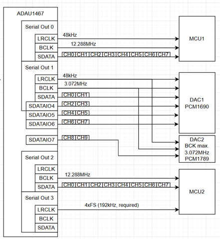
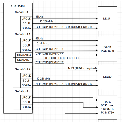
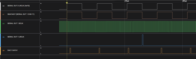
maybe i have a workaround. I set SDATAIO7 to send out channel 8-11 of serial-out-1. I set the outputs (24,25,26,27) into 32-Bit format mode. Then I sourced the the bit pattern 0x0001FFFE (shifted by one due to I2S mode). This seems to generate exactly a 192kHz clock which is in sync with the 4xFS LRCLK of serial-out-3. This would free up serial-out-3. Giving us the option to send data to DAC2.
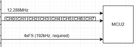
Below is the blockdiagram and next to it the logic trace.
Do you think this could work?
Best regards,
Eric
Hello Eric,
I am somewhat confused by all these different requirements and what you are trying to do?
I would like to focus on one little thing. This:
You are showing TDM-8 for audio data, 12.288MHz BCLK and a 192kHZ fs???
That just will not work.
If you were to use a 32 bit channel slot width, then with 8 channels that would be 8x32=256 data bit slots.
Then multiply that by the sampling rate of 192kHz would give you a bit clock rate of 49.152MHz which is WAY too high!!
There is no way you can get that to function for many reasons.
The max bit clock frequency out of the pin is 24.576MHz.
Let's not even start to talk about the difficulty of getting the signal integrity good enough to not get lots of data errors.
So the max for TDM-8 will be 96kHz with a 32 bit slot width.
Yes, you could go with a 16 bit data slot and get it up to 192kHz but as I alluded to, the PCB layout of the clock and data lines will be tough to keep the signal integrity in good shape.
The 12.288MHz BCLK you show is for TDM-8 at 48kHz fs.
As to your question about using the SDATAIOx pins, there was an issue with the design of the chip which I think would not make it possible to use seven of these pins along with the main SDATAIO pin, to output 16 channels of I2S signals. I would have to experiment with that on the bench to see if it can be done but I am doubtful.
We will see if Harish sees some things I am missing here.
Thanks,
Dave T
EricSa said:
8 SDATA pins (8x2channels)
Do you have a DAC chip that accepts 8 data lines? ... or would you be sharing the MCLK and BCLK across multiple chips with 4 or fewer data lines per individual chip?
[Edit] I see that you're communicating with an MCU, so I assume it has the ability to configure 8 data lines with shared clocking?
Hey DaveThib and SoundConsulting ,
thanks a lot for your feedback. I will try to answer all the open questions.
Reply to Dave:
"You are showing TDM-8 for audio data, 12.288MHz BCLK and a 192kHZ fs???"
This is almost correct and a bit hard to explain. But in the end serial-out-2 transmits a normal TDM8 stream with 48khz (12.288MHz). But we have to feed an additional 192kHz LRCLK, which is in sync with serial-out-2, to the MCU2. So the requirement here would be: Normal TDM8 Stream (48kHz LRCLK, 12,288MHz BCLK) + 192kHz LRCLK in sync from anywhere else.
We recently used serial-out-3 to generate the additional 192kHz LRCLK while keeping the BCLK and SDATA of it unused. Now we have the requirement to source a second DAC (DAC2) with 2 channels. Thats why we would like to free serial-out-3 up to use it for the DAC2.
The only solution to free it up is by get rid of the LRCLK from serial-out-3 and generate the 192kHz LRCLK in a different way. I have no other idea as the workaround with the bit pattern as described in my last post. Or is there any other way to generate a 192kHz LRCLK?
"As to your question about using the SDATAIOx pins, there was an issue with the design of the chip which I think would not make it possible to use seven of these pins along with the main SDATAIO pin, to output 16 channels of I2S signals. I would have to experiment with that on the bench to see if it can be done but I am doubtful."
I've checked the datasheet and it looks that it is really only possible to send 8 channels by using SDATA + 3x SDATAIOs (ch0,1,4,5,8,9,12,13). It would be great if could send 16 or ar least 10 channels by using SDATA + 4x SDATAIOs. In this way we could feed DAC2 from serial-out-1.
Reply to SoundConsulting:
"Do you have a DAC chip that accepts 8 data lines? ... or would you be sharing the MCLK and BCLK across multiple chips with 4 or fewer data lines per individual chip?"
This was a request sending 16 channels via serial-out-0/1. The datasheet just mentions that you can send 16 channels via TDM16 1x DATA pin, TDM8 2x DATA pins or TDM4 4x DATA pins. But not the option I2S 8x DATA pins. If this would be possible, we could source our DAC from serial-out-1 and keep everything else as it is.
Best regards,
Eric
Hello Eric,
I believe you must have used all serial input ports, and no port is free in the serial input side, otherwise it would be very straight and easy.
So, the method of yours using SDATAIO7 as clock, did you try using it with any of the functions in your system? does it work fine?
I can see a way but I'm not sure if it's possible in your hardware, it does concern signal integrity issues. But you can give it a try if possible.
So, the serial input port 0 and serial input port 2 both are at same configuration. They both run at TDM8 (12.288MHz and 48KHz), so instead of using port 2, we can place those 8 channels into serial port 0 (from Ch 8-15). So, serial port 0's primary pin carries a TDM8 to MCU1 which you already configured and use one SDATAIO pin with port 0 to transmit another TDM8 to MCU2, now the tricky part, you have to share the serial port 0's clocks to MCU1 and MCU2. Now two TDM8 have been sent to MCU1 and MCU2. So, you have port 2 free that you can utilize either for DAC2 or creating 192KHz clock.
In schematics, delete the port 2 outputs (Ch 32-39) and replace those with port 0's output (Ch 8-15).
Taking serial port 0's clock and sharing them between MCU1 and MCU2 is the only thing you have to work out. Is it possible with your hardware? You can use a pin buffer once you verified the test setup working. we do have pin drive strength settings too incase if that helps.
It's been a long day for me, so let me know if I obviously missed anything.
Regards,
Harish
Hello Harishgowtham ,
thanks for the good feedback. I guess you have pointed out another solution. At the moment the data format of serial-out-0 and serial-out-2 is a little different.
serial-out-0 (I2S Mode / BCLK delay by 1)
serial-out-2 (Left Justified)
But maybe I am able to change it on serial-out-0 to left justified. If so it could work. Then serial out 2 is completly free. Thanks for this hint.
Regarding your question: "So, the method of yours using SDATAIO7 as clock, did you try using it with any of the functions in your system? does it work fine?"
Yes we tried it here and it works perfect. The only difference between the "real LRCLK" and the "Fake LRCLK" via SDATAIO7 is that the "Fake LRCLK" starts a bit later. I guess this is because the data is initialized later than the serial-ports. Is this right?
Do you see any potential problems in using the SDATAIO7 as "Fake LRCLK"?
(don't wonder why serial-out-3 LRCLK is now at 48kHz, here we already configured it for the DAC2, but also with 4xFS 192kHz it starts earlier as the "Fake LRCLK"),
Best regards,
Eric

Please log in to reply.