Request for Review of ADAU1451 DSP Audio Architecture
Dear Analog Devices Support Team,
I would like to ask for your support in reviewing the audio architecture of our system using the ADAU1451 DSP.
System overview
Host processor: Rockchip CM3588
DSP: ADAU1451
Power amplifiers
4 × TAS2780
1 × TAS6421-Q1 (TAS6421QDKQRQ1)
Audio interface
The I2S output from the Rockchip CM3588 (SDO, LRCK, SCLK) is connected to the ADAU1451 I2S input:
SDO → SDATA_IN
LRCK → LRCLK_IN
SCLK → BCLK_IN
The I2S outputs of the ADAU1451 are connected to the power amplifiers as follows:
OUT3 → TAS6421-Q1
OUT2 → 1 × TAS2780
OUT1 → 1 × TAS2780
OUT0 → 2 × TAS2780
Could you please help review whether this I2S configuration and routing are appropriate for the ADAU1451?
If there are any recommended configurations or potential issues, we would greatly appreciate your advice.
The schematic diagram is attached.
Could you please help review it and provide your comments?
Thank you very much for your support.
Best regards,
Phong
Audio Signal Processors
tas2780
adau1451
hardware
tas6421
processors and dsp
SigmaDSP Audio Processors
Processors and Microcontrollers
Show More
Hello Phong,
For some reason the PDF is low quality and blurry.
Can you send it to me in a private message? Just make sure to also send me a friend request so I can respond.
I do want to mention that we have some really great power amps that you should consider using.
Dave T
Dear Dave,
I tried opening it on another computer and another phone, and there was no problem. You should download the file using a computer and then open it.
Hello Phong,
Your schematic looks good overall. However, I have a few suggestions:
1. SELFBOOT Pin Configuration
I noticed that the SELFBOOT pin is pulled up with a resistor. On the EVAL board, there is a physical switch that allows SELFBOOT to be set to either logic low or logic high.
During programming through SigmaDSP, the SELFBOOT pin must be set to Low. This is because the chip resets during the programming process and may attempt to reload data from an uninitialized EEPROM before the write process begins, which could lead to the issue.
After the EEPROM has been successfully written, the SELFBOOT pin should be set to High, and the SigmaDSP should be restarted using a reset or a power cycle. On the EVAL boards, this is typically done by flipping the physical switch after the write operation is completed.
2. I2S Input Connection
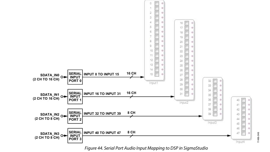
I also noticed that your I2S input is connected to Serial Port 3. Is there a specific reason for choosing this port?
Instead of Port 3, you could consider using Serial Port 0 as it supports TDM16, whereas Serial Port 3 supports only TDM8. Using Port 0 might provide more flexibility for future requirements.
Please refer to the image below for reference.
Regards
Aravindh
Please log in to reply.