TDM8 Connection on ADAU1467 Rev.B Evaluation Board (Brooklyn 3 + AK5578 Configuration)
I am currently evaluating an ADAU1467 Evaluation Board Rev.B and am having trouble getting the TDM connection to work correctly.
If anyone has used a similar configuration or is aware of any important setup considerations, I would greatly appreciate your advice.
[Devices Used]
• ADAU1467 Evaluation Board Rev.B
• Dante Brooklyn 3
• AK5578 ×2
[System Configuration]
The Brooklyn 3 is configured as the clock master.
Clock Connections:
• Brooklyn 3(Master)→ ADAU1467 (Slave)
- MCLK (Pin 25, MCLK)
- BCLK (IN0)
- LRCLK (IN0)
- DATA (IN0)
• ADAU1467(Master)→ AK5578 (Slave)
- MCLK (Pin 27, CLKOUT)
- BCLK (OUT1)
- LRCLK (OUT1)
- DATA (OUT1)
Audio data is connected using TDM.
[Format]
• TDM8
• 256fs
• Left-Justified 24-bit
• MCLK = 24.576MHz
• BCLK = 12.288MHz
• LRCLK = 48kHz
[Issue]
I am attempting to establish communication between the AK5578 devices and the Brooklyn 3 through the ADAU1467, but the system is not operating correctly.
In particular, it appears that the SDATA signal from the ADAU1467 to the Brooklyn 3 is not being transmitted.
The input clocks are present, and the DSP appears to be running properly. However, no audio is received on the Dante Controller side.
My main concern is determining the correct serial port configuration for the ADAU1467 when the Brooklyn 3 is used as the clock master.
If anyone has experience with a similar setup or has suggestions on what to check, I would greatly appreciate your guidance.
Thank you in advance.
Thread Notes
DaveThib - Moved from Precision Microcontrollers to SigmaDSP Processors & SigmaStudio Dev. Tool. Post date updated from Friday, August 7, 2026 2:17 AM UTC to Friday, August 21, 2026 6:18 PM UTC to reflect the move.
dsp
hardware
adau1467
processors and dsp
sigmastudio
tdm
Processors and Microcontrollers
Show More
Hello ,
I just moved this post to the correct space on the forum. That is why I did not see this.
Can you attach your project?
Do you have an oscilloscope to look at the signals?
I will have more questions.
Dave T
Hello Dave T,
Thank you for your reply.
I am reposting my question below for reference.
>
I am currently evaluating an ADAU1467 Evaluation Board Rev.B and am having trouble getting the TDM connection to work correctly.
If anyone has used a similar configuration or is aware of any important setup considerations, I would greatly appreciate your advice.
[Devices Used]
• ADAU1467 Evaluation Board Rev.B
• Dante Brooklyn 3
• AK5578 ×2
[System Configuration]
The Brooklyn 3 is configured as the clock master.
Clock Connections:
• Brooklyn 3(Master)→ ADAU1467 (Slave)
- MCLK (Pin 25, MCLK)
- BCLK (IN0)
- LRCLK (IN0)
- DATA (IN0)
• ADAU1467(Master)→ AK5578 (Slave)
- MCLK (Pin 27, CLKOUT)
- BCLK (OUT1)
- LRCLK (OUT1)
- DATA (OUT1)
Audio data is connected using TDM.
[Format]
• TDM8
• 256fs
• Left-Justified 24-bit
• MCLK = 24.576MHz
• BCLK = 12.288MHz
• LRCLK = 48kHz
[Issue]
I am attempting to establish communication between the AK5578 devices and the Brooklyn 3 through the ADAU1467, but the system is not operating correctly.
In particular, it appears that the SDATA signal from the ADAU1467 to the Brooklyn 3 is not being transmitted.
The input clocks are present, and the DSP appears to be running properly. However, no audio is received on the Dante Controller side.
My main concern is determining the correct serial port configuration for the ADAU1467 when the Brooklyn 3 is used as the clock master.
If anyone has experience with a similar setup or has suggestions on what to check, I would greatly appreciate your guidance.
Thank you in advance.
>
In summary, I would appreciate your guidance on how the MCLK, LRCLK, BCLK, and DATA signals should be connected between the ICs.
I have an oscilloscope and can provide signal measurements if necessary.
I look forward to your questions and any advice you can provide.
Thank you for your assistance.
Hello Miharu,
I have couple of questions, could you please answer them?
MIHARU said:
• ADAU1467 Evaluation Board Rev.B
• Dante Brooklyn 3
• AK5578 ×2
[System Configuration]
The Brooklyn 3 is configured as the clock master.
Clock Connections:
• Brooklyn 3(Master)→ ADAU1467 (Slave)
- MCLK (Pin 25, MCLK)
- BCLK (IN0)
- LRCLK (IN0)
- DATA (IN0)
• ADAU1467(Master)→ AK5578 (Slave)
- MCLK (Pin 27, CLKOUT)
- BCLK (OUT1)
- LRCLK (OUT1)
- DATA (OUT1)
Audio data is connected using TDM.
[Format]
• TDM8
• 256fs
• Left-Justified 24-bit
• MCLK = 24.576MHz
• BCLK = 12.288MHz
• LRCLK = 48kHz
[Issue]
Here, as per your signal flow,
I can understand that Dante is the master sending TDM8 clocks and data to input port 0 of ADAU1467 and the ADAU1467 passes it to serial output port 1 which is master, it sends TDM8 clocks and data to AK5578 (slave). But the AK5578 seems to be an ADC, but it does have TDM input pin, so I guess you are trying to get TDM16 out from AK5578 (8 ch from DSP and 8 ch from analog pins). Is that right?
MIHARU said:
In particular, it appears that the SDATA signal from the ADAU1467 to the Brooklyn 3 is not being transmitted.
Here, as per your previous statement, the Dante has to send clocks and transmit data to ADUA1467.
The flow is Dante---> ADAU1467, and not ADAU1467---->Dante. If Dante is not sending SDATA out, then you have to look at the Dante side. DSP can't transmit data onto serial output 1 if it didn't receive in serial input 0 in the first place.
MIHARU said:
The input clocks are present, and the DSP appears to be running properly. However, no audio is received on the Dante Controller side.
Again, Dante controller has to send data out to DSP, Dante shouldn't receive audio.
Please make a block diagram of your connection and share, if we didn't understand your connections correctly.
MIHARU said:
My main concern is determining the correct serial port configuration for the ADAU1467 when the Brooklyn 3 is used as the clock master.
That's the reason why Dave asked for the sigma studio project, it would help us to find any configuration related problem.
MIHARU said:
I have an oscilloscope and can provide signal measurements if necessary.
Please probe serial input 0 and see if the Dante is properly sending TDM8 clocks and data. Please refer this post for taking proper screenshot of the signal.
Since you are using 24.576MHz as MCLK, you have to change the PLL, the default project's PLL setting is for 12.288MHz. So, attaching your project would be greatly appreciated. If you can't send it on the public forum, Please DM to either Dave or me. Please send a friend request so that we can respond in Private message.
Regards,
Harish
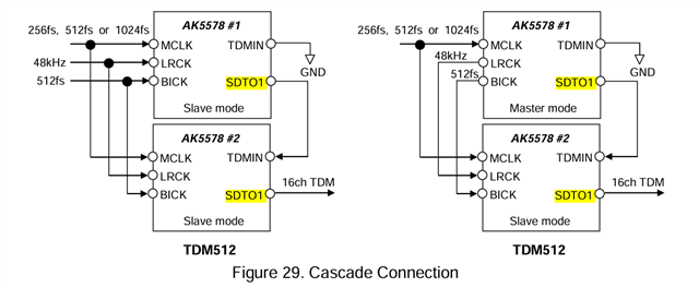
Hello Harish,
Thank you for your reply.
Please find my answers to your questions below.
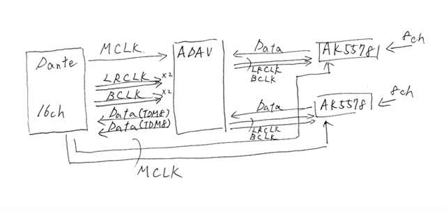
Regarding the Block Diagram
I have drawn a hand-sketched block diagram as shown below.
The MCLK signal is output from the Dante module and distributed into three branches using a clock buffer IC. The three outputs are connected to the ADAU and the two AK5578 devices.
For LRCLK and BCLK, the signals are also distributed using buffer ICs and split into two branches, which are then connected to the ADAU ports (LRCLK_OUT0, LRCLK_OUT1, BCLK_OUT0, and BCLK_OUT1).
Since the ADAU output ports are configured as slaves, the clock signals are being fed into these output ports.
After that, the signals are routed from the ADAU ports (LRCLK_IN0, LRCLK_IN1, BCLK_IN0, and BCLK_IN1) to the AK5578 devices.
Since the ADAU input ports are configured as masters, the clock signals are output from these input ports.
The AK5578 devices output TDM8 audio data, which is connected to the ADAU ports (SDATA_IN0 and SDATA_IN1). The corresponding outputs (SDATA_OUT0 and SDATA_OUT1) are then connected to the Dante module.
Regarding SigmaStudio
I have attached the project file.
ADAU.ssprj
Regarding Oscilloscope Measurements
I was able to observe the TDM8 signal coming from the AK5578 using the oscilloscope.
The audio signal flow is:
AK5578 → ADAU → Dante
Please let me know if you need any additional information.
Hello Miharu,
Thanks for the block diagram, it is really helpful. We usually start ADC in the left side then DSP then DAC in right end, so it took me a while to realize your diagram. Anyway, it's really helpful and clear.
I see you are using SS+, could you tell me which version?
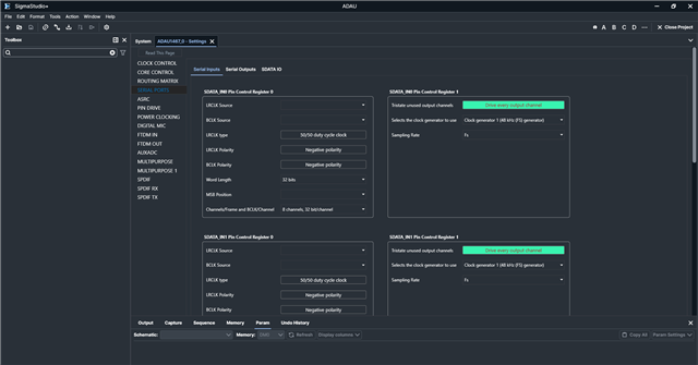
I loaded the project in SS+ 3.3.0, but it's weird that some tabs are empty. I have never seen something like this before. So, I don't know what set in those tabs.
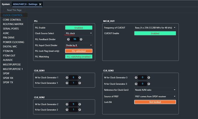
Anyway, I did notice something in the PLL section of your project. The 'input clock divider is set for 4' which is for 12.288MHz.
When your MCLK In is 24.576MHz, then your input clock divider should be 8. please find the updated screenshot below for your PLL settings. please try this and get back.
Regards,
Harish
Hello Harish,
Thank you for your reply.
Also, thank you for the screenshots.
They are very helpful and provide valuable reference information.
The application version is SigmaStudio+ 3.4.0.
Best regards,
Please log in to reply.