DC coupled input on ADAU1761
Hello there,
is it possible to use a DC coupled input on the ADAU1761 in a single-ended input configuration? Specifically the line input pins LINP, LINNP, RINP, RINNP ? I'd like to be able to measure the DC offset of my signal. My goal is to build a simple lock-in amplifier based on the ADAU1761 with SigmaDSP.
Thank you
Best,
Simon
Audio Signal Processors
biasing
dc offset
dc coupling
SigmaDSP Audio Processors
adau1761
line in
Show More
Hello Simon,
Yes, the ADAU1761 ADCs work down to DC. However, they weren't designed for precision DC measurements.
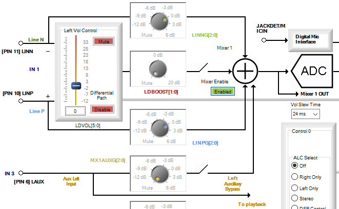
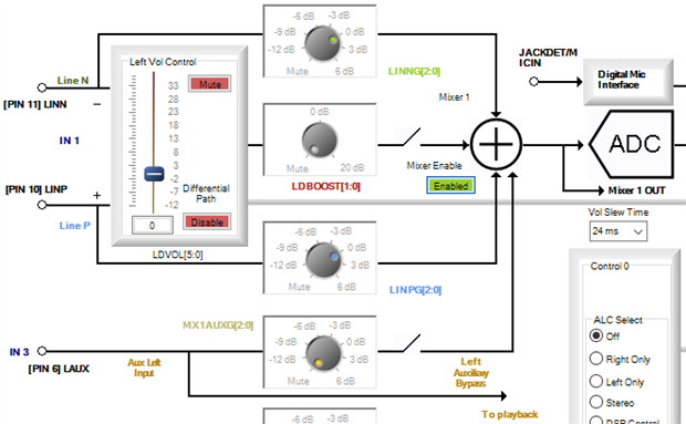
This chip includes a versatile record (input) signal path, most of which you'll want to disable to use the ADCs as desired. This screenshot from SigmaStudio shows the path for the Left ADC, the Right ADC path is similar. With these two ADCs you can measure two independent signals.
Since you wish to use the differential input pins in a single-ended mode, I disabled the differential amplifier and set up a direct path from the LINN and LINP pins to the adder and ADC. In this configuration the + and - (N and P) designations don't apply; both pins go straight to the adder and ADC.
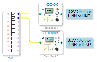
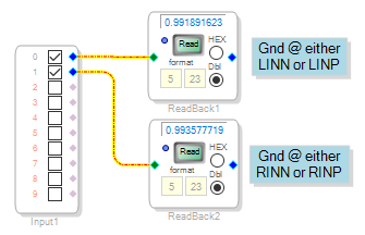
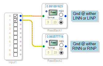
I tried the simple project shown below and used a clip lead to drive each input pin to Vcc and Gnd -- to see if the ADCs can pass DC. With either pin connected to Vcc, the ADC reads full-scale negative (-1.00) as shown at left below. With either pin grounded, the ADC reads nearly +1.00 (below right). Note that the Left and Right ADCs give slightly different readings, neither exactly 1.00 -- audio ADCs are not meant for precision DC measurements. In fact the gain error can be as much as -12% if I read the data sheet correctly. -12% amounts to -1.1 dB, not significant in the audio realm but rather much in a measurement environment. In the examples below, the Vcc and Gnd inputs have saturated the ADCs -- actual DC input for full-scale positive and negative readings occur slightly above Gnd and below Vcc respectively. You'll need to calibrate your gain accordingly.
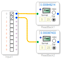
With the ADC inputs open, they self-bias to midway between Vcc and Gnd, resulting in a reading that's near, yet not exactly zero:
So you can run the inputs down to DC, with reservations.
Best regards,
Bob

Hello Simon,
Bob gave you an excellent response. Let me add one more thing.
If you reference the Op-Amps to the CM pin voltage, then you can obtain a positive or negative reading from the ADC. This may be handy if this is for a servo loop. In addition, if you devise a method for slight adjustments from this CM voltage, then you can probably calibrate out the DC offset of the converter and get a little better accuracy.
If you do use the CM pin, keep in mind that this is a high impedance source. So if you are driving two channels or driving a lower impedance load, then you will want to buffer this CM signal with a voltage follower.
You also will want to disable the HPF that is built into the ADC. It is off by default just make sure it is not changed.
Dave T
Please log in to reply.