One quartz and one eeprom for two adau1701.
Hello everyone.
I would need to use 2 ADAU1701 in the same project.
The first use a sample rate at 96Khz the second at 48Khz.
2 questions:
1) you can derive the clock for the second ADAU from the first ADAU so you
only use a quartz, this belief is possible.
If so how?
2) you can link the 2 hex files and write them on the same eeprom, so that
the second ADAU performs but starting from a precise address when the first
ADAU has finished loading the data for its program into its memory.
The process should be as follows:
Feeding the circuit the first ADAU during the process of uploading its data
blocks the second ADAU "think" when it uploaded its data unlocks the second
ADAU which will have to do but starting from a specific address and not from 0
If so how?
Lastly, the available space for the hardware is very limited, can you use the
two ADAUs as visible in the attached image by connecting the two ADAU pins in
parallel?
Thanks
Piero
Audio Signal Processors
clock
SigmaDSP Audio Processors
butstrap
adau1701 sigmastudio
adau1701
Show More
Thanks for response Dave,
the two programs are different so I have to find other solutions.
I will use a microcontroller to perform all the logic functions that dsp now, which sampling at 96Khz can only make 512 instructions.
I have no other possibility, the project is at risk because I use 511 instructions and I have nothing to optimize.
Hello Piero,
1) you can derive the clock for the second ADAU from the first ADAU so you
only use a quartz, this belief is possible.
If so how?
You can use the serial port BCLK output as an MCLK to another part. You will have to set it to the proper frequency but it is possible to do this. See the "Using the Oscillator" section of the datasheet.
2) you can link the 2 hex files and write them on the same eeprom, so that
the second ADAU performs but starting from a precise address when the first
ADAU has finished loading the data for its program into its memory.
The process should be as follows:
Feeding the circuit the first ADAU during the process of uploading its data
blocks the second ADAU "think" when it uploaded its data unlocks the second
ADAU which will have to do but starting from a specific address and not from 0
If so how?
It is not possible to change the address that it boot up from. This is "hard-coded" into the hardware and cannot be changed.
It is possible to boot both off the same program but they would have to be running at the same sampling rate. There could be nothing different between the programs. How you would do that is to set one of the MP pins to be a GPIO output. Then route that pin to the reset line of the other DSP. So then you will need an inverter on the GPIO pin since on power up the pin is high and you will want it to be externally inverted to a low to hold the other DSP in reset. So while the first DSP is reading from the EEPRPM the second is held in reset. Once the program finishes loading and starts to run, the DSP program will be setup to keep the GPIO port low. So the first time the program runs it lowers the pin. At this point the first DSP has completed booting and is no longer an I2C master.
So then the second DSP wakes up and starts loading in the program from the EEPROM. The only problem with this arrangement is that if you use any writeback cells to store settings when power goes down, there will be a clash between the two processors as they try to save their settings to the same EEPROM and to the same address within the EEPROM. So you cannot enable the writeback function.
Lastly, the available space for the hardware is very limited, can you use the
two ADAUs as visible in the attached image by connecting the two ADAU pins in
parallel?
Your image was of just one DSP and only the power pins. So I do not understand the question.
Also, you are using the same 3.3V supply for both the IOVDD and AVDD. This is OK but you may see some reduced performance from some of the noise on the IOVDD line. If you do keep it this way you do not need two 10uf caps on the 3.3V line. You only need one.
If you are asking to parallel the power to the two, yes, the IOVDD and AVDD can be the same power supply. The DVDD cannot be shared between the two DSPs. Only DSP per regulator circuit.
Dave T
Hello everyone,
can I connect 2 DAU1701 as shown in the attached image?
I have huge space problems, hardware is very small and I have to put as few components as possible.
Dave has already answered me earlier explaining how to get the clock from the first to the second DSP and its modification on the appropriate registers.
I could use a microcontroller, as first written, but the costs are almost equal to the use of a second DSP.
The use of 2 DSPs is beneficial for my client because through SigmaStudio in the future it can make simple modifications to the software, but the microcontroller is lying to other emulators and various complications.
The application is not intended for high-quality audio or even high sound power, so even some noise can be accepted.
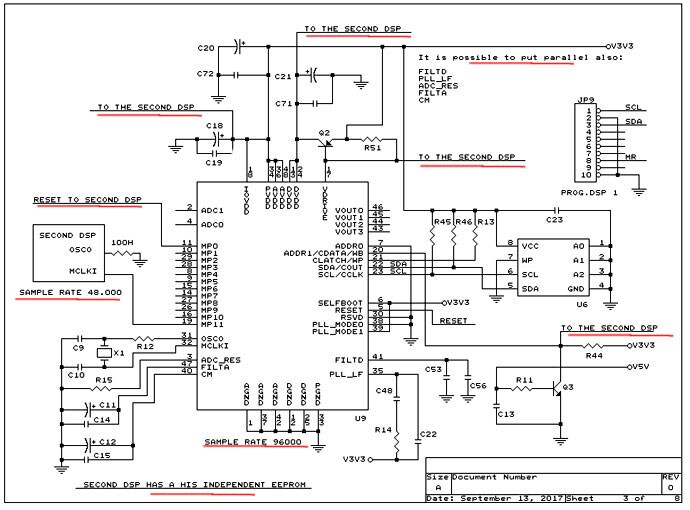
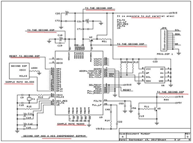
Hello Piero,
It is not recommended to parallel the regulator. Look into using one external regulator to drive both parts.
You can share the 10uf caps on the IOVDD and AVDD but each pin MUST have a 0.1uf cap mounted close to the pin on the same side of the PCB as the part.
No. you absolutely cannot parallel any of the following: FILTD, PLL_LF, ADC_RES, FILTA, and CM.
Yes, you can share the writeback trigger.
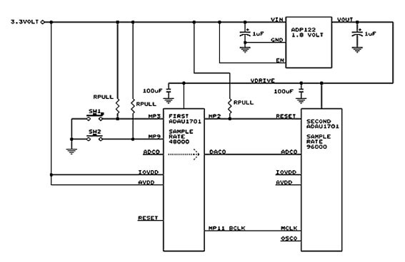
If you set the BCLK output as a master and set the serial port to produce 12.288MHz then you can drive the MCLK of the other part from MP11.
The reset off of a MP pin should also work.
Dave T
Thanks Dave
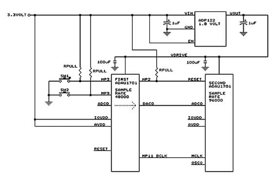
Please confirm if the design is correct
MP2 goes low when dsp 1 has loaded its program by allowing dsp 2 to load its
program, is it correct?
In the second dsp the OSCO pin was left open?
The first DSP has a sampling rate of 48000 Hz the second instead of 96000.
How to set MP11 of the first dsp to get 12.288MHz to send to MCLK of the
second dsp?
Please log in to reply.