ADAU1452 Eval board filters & output problems
Hi,
I am new with this board and with DSP,
so please forgive me if my questions sound stupid.
I want to use this evaluation board as a crossover for experimentation.
Specifically I'd like to feed the board with data via optic cable and output
2 pairs analog channels: Left & Right Low and Left & Right mid high
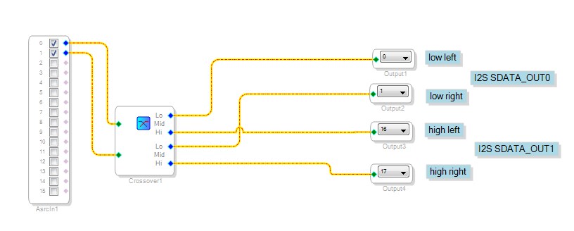
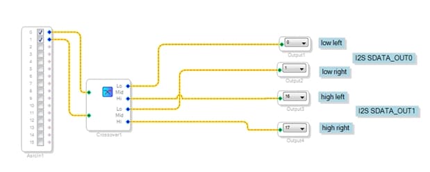
I designed the attached schematic after reading the board's documentation.
So, I was expecting to have at the outputs OUT1R/L the left and right bass channels
and at OUT2R/L the left and right mid and high channels.
Instead at OUT1 I get all frequencies and at OUT2 I get nothing.
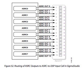
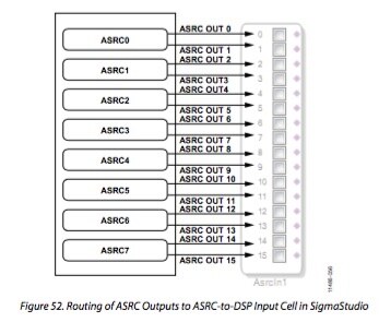
According to the instructions for setting up the SPDIF IN, I have to insert the ASRC block into the schematic.
I noticed that this block is called by default Asrcin1. While at the hardware configuration tab, instructions say that I should configure
ASRC0. Could this be the problem?
Any ideas?
Nikitas
Audio Signal Processors
adau1452
SigmaDSP Audio Processors
eval-adau1452miniz
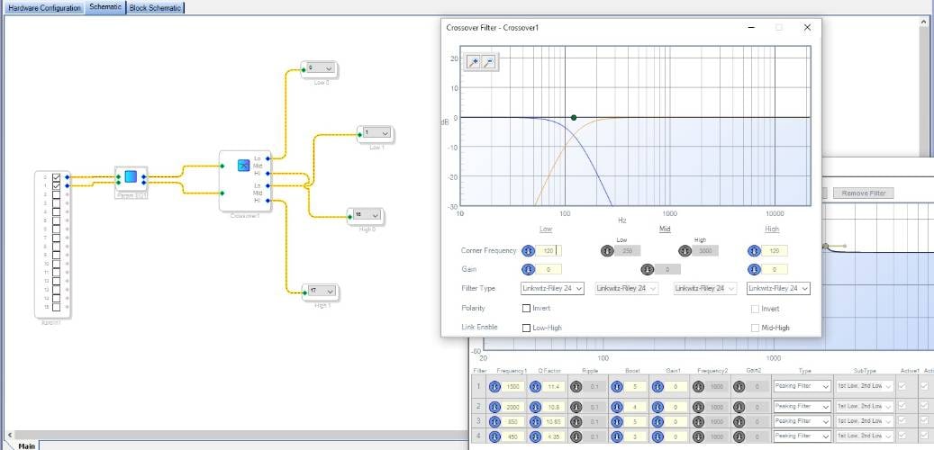
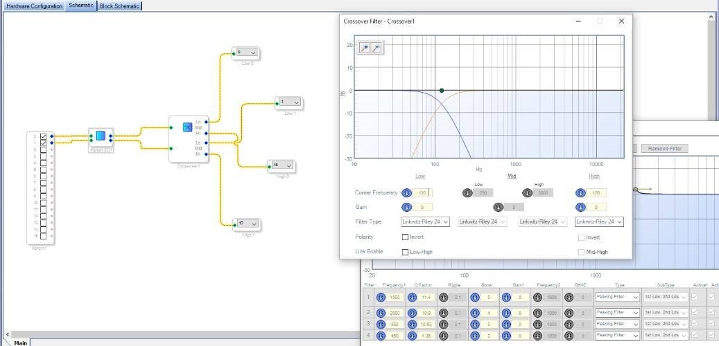
Looking at figure 43 (ADAU1452 manual), I have the impression that I should route the processed signal from the Asrcin1 to SDATA_OUT0 and SDATA_OUT1. Although I can't find a block that can do this.
The cell name below a block is just an identifier.
If you take a look into the output files from sigma studio you can find these cell names again.
ASRC (page 46).
You can wire spdif to any of these ASRCs.
For power saving you can disable for example ASRCBANK0_PWR(ASRC0-3) and/or ASRCBANK1_PWR(ASRC4-7).
This question has been assumed as answered either offline via email or with a multi-part answer. This question has now been closed out. If you have an inquiry related to this topic please post a new question in the applicable product forum.
Thank you,
EZ Admin
Please log in to reply.