Concerned about crystal/clock swing level/ ADC noise issue.
Hello, I'm slightly concerned that the amplitude of my clock signal is too great.
Attachment 'PIN41_27PF' shows the signal at pin 41 of my ADAU1446 (after the 100R resistor), measured using an inch long ground lead. Scope set to .1V/div with 10x probe, so 1V/div visible. The lower half of the clock swings to around -0.4V, I don't know if this pin counts as a digital input, if it does, maximum input level is -0.3V. Should I be worried?
Attachment 'CLKOUT' shows the signal on the CLKOUT line, after a 100R series resistor, lower values give a 'less desirable' trace. Does this look OK?
These were taken with 27pF for the crystal compensation caps, using 22pF looks much the same. I daresay I could decrease further (or increase) the cap value and reduce the swing, but at the expense of stability?
Attachment 'PIN42' shows the signal at pin 42, the side of the crystal without the 100R resistor.
This has all come about because I'm seeing a lot of noise from my ADC, -54dBFS, which doesn't appear to be on the analog inputs. Measured using the level detector within sigmastudio. Have used all recommended decoupling and filtering etc...So looking to see where else the problem might be. Curiously sigmastudio almost always shows the value as -54 but occasionally shows it to be -60, with no change in hardware. I have the ADAU1445 set to be master, by changing it to be slave, noise reduces by 6dB, not sure what to make of that.
Attachment BCLK shows the BCLK signal to the ADC, (DSP is master). The trace is about an inch long and I can't noticeably that trace by tweaking the value of the series termination resistor (0r, 10r, 22r, 33r, 47r, 56r, 68r, 75r). Which has me wondering if there's a clock issue.
Any thoughts, thank you.
Audio Signal Processors
adau1446
adau1445
SigmaDSP Audio Processors
Hello Alex,
To fix the high no-signal reading on your Level Meter, add a DC Block filter directly before the meter in your SigmaStudio project. It's not commonly known that the Level Meters do respond down to DC! There's enough residual DC coming from the ADC to show a reading in the range you're measuring, typically 0.1 -- 1.0 percent, or -60 to -40 dB. Thus, often the DC Block filter makes a dramatic difference -- for an example, see https://ez.analog.com/message/211193#211193
I very much suspect that your ADC "noise" is actually this residual DC, which is quite normal for audio ADCs. Thus if you try the filter, likely you'll see this issue go away. In this case your other concern -- the crystal signal -- reduces to merely whether the swing at this pin is somehow adversely affecting the IC's oscillator circuit. As long as you're using the recommended components and have followed the layout practices suggested here:
SigmaDSP PCB Layout Best Practices
the thing should work fine (of course, it would be nice if an ADI HW engineer would confirm that the small negative excursions here are normal). Engineers frequently get themselves in trouble by ignoring data sheets, much more rarely by following them! The crystal oscillator is a self-contained design -- so really its signals, even those at the recommended external components, should be ADI's concern, not yours. I also suspect that, despite your care in scoping this signal, that some of this negative overshoot could still be a measurement issue -- especially if your scope's BW is much in excess of 100 MHz. Being an old switching power supply engineer I've seen this all too often.
Hope this helps!
Bob
Ah Bob! Thanks, always so helpful! On the previous iteration of my board I had the ADC's internal HPF enabled, i disabled it for this version but forgot I had done so, good grief!
Another 'issue' has now cropped up, with DSP as master, it works fine, when I put the ADC into master mode I get some very large...oscillations, I suppose they are, at about the same amplitude of the test signal. At 1kHz test signal, there are two oscillations at about 13k and 18k (would need to check again). The obvious solution is to just keep the DSP as master but I'm curious as to why it does this and if it's a sign or something not quite right. Any ideas?!
Hello Alex,
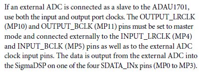
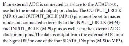
I have only limited experience with I2S connections so may not be of much help. The ADAU1701 data sheet does indicate that its clocks are set up differently with external ADCs in mater vs. slave modes -- with the ADC as mater, you need to undo the stuff shown below
Perhaps if you ask about this issue in a new thread, your question would get more visibility and an ADI support engineer could help. I know of at least one who is quite knowledgeable with digital audio, but it's not my place to volunteer him (or anyone else for that matter).
Best regards,
Bob
This question has been assumed as answered either offline via email or with a multi-part answer. This question has now been closed out. If you have an inquiry related to this topic please post a new question in the applicable product forum.
Thank you,
EZ Admin
Please log in to reply.