ADAU1701 (EVAL-ADAU1701MINIZ) i2c write issue
Hello everybody!
I am tryng to use a TI MSP430F6638 microcontroller to comunicate via i2c with my EVAL-ADAU1701MINIZ.
I set the i2c rate at 400KHz, and I placed two 2k2 resistors connected to 3v3 to pull-up the i2c bus.
The SCL and SDA are connected respectively to the pin 1 and 3 of the connector J8 ( see EVAL-ADAU1701MINIZ datasheetpage 8)
But it is not working when I try to write into the EVAL-ADAU1701MINIZ.
I send the address but I don't receive any aknowledge by the DSP. By using the oscilloscope I can see that the correct address is sent (0x68), but the ADAU1701 doesen't send the acknowledge.
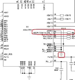
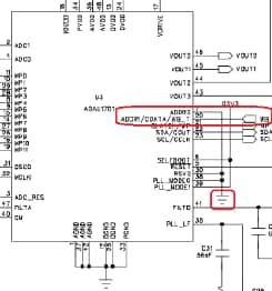
Since the ADDR0 and ADDR1 pins of ADAU1701 are connected to 0, the address should be 0x68. Anyway I tryed also the others possible addresses (0x6A, 0x6C, 0x6E) but it still doesent't work.
Of course I am sending the 7 bit address, for example I send 0x34 in order to have 0x68 on the bus, in fact the address I see using the oscilloscope is correct.
Is there anyone that experienced the same issue? is there any particular setting to do on the ADAU1701 or on the host MCU?
Please, do you have any suggestion?
I have wasted a lot of days in order to solve this problem!
Thank you in advance
Vito Pirro
Audio Signal Processors
eval-adau1701miniz
i2c issue
i2c_address
SigmaDSP Audio Processors
i2c write
SigmaDSP
adau1701
Show More
Hello Vito,
It seems like you are on the right path. I did a quick test on my EVAL-ADAU1701MINIZ board, which assumes ADDR0/ADDR1 are tied low. I checked the USBi firmware and do see that when I2C communication is used, the ADDR1/CDATA pin is driven low by the Cypress microcontroller. So this defaults to a default chip address 0x68.
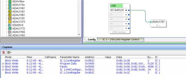
Connecting to SigmaStudio assumes 0x68, and I get a ACK back from the ADAU1701.
Here is a capture of the first block write, Core Register address 0x81C:
I see you tie ADDR0/CDATA to GND and are correctly using SCL as pin 1 and SDA as pin 3 on J8.
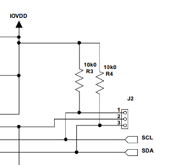
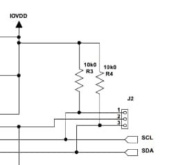
Then only difference I see is that the USBi uses weaker pull-down resistors with larger 10K-ohm value.
Also do you have the GND pin on the J8 connector is tied to a digital GND on your TIMSP430 board?
-JT



Hi john!
Thank you very much!
The problem was just in the pull-up resistor values. In fact I noticed that the ADAu1701 evaluation board has already two 10k pull-up on the i2c bus, so the result was that I had 2k2 and 10k in parallel = 1k9 !
Now it works correctly!
Again, thank you very much.
Kind regards,
Vito
Please log in to reply.