ADAU1761 I2C only works after programming device
I've done a bunch of work with my ADAU1761 board and now I'm ready to have my microcontroller program it. I've read the presentation/guide on how to do it from analog. My codec programs fine when I use SigmaDSP.
I built up some I2C functions to test the interface between the codec and my mcu. When I try to read a control register to verify my connection I get ACKS, but the data always comes back 0x00. But then I thought to load the codec using SigmaDSP first, and then my reads worked fine (default values shown in the datasheet were returned).
So I feel like maybe you have to do a bunch of writes to configure clock and start the processor before you can read control registers? Is that true? Is there a simple register I can read for verification? It would be nice to have a register to read that said yes this is an ADAU1761.
Thank you.
Audio Signal Processors
SigmaDSP Audio Processors
adau1761
Hi,
I have moved this discussion from the Processors and DSP community to the SigmaDSP Processors and SigmaStudio Development Tool community. P;ease continue the discussion here.
Regards,
Craig.
Hi Eric,
I apologize for the delay here due to ADI's shutdown the last 2 weeks of December. Have you resolved this?
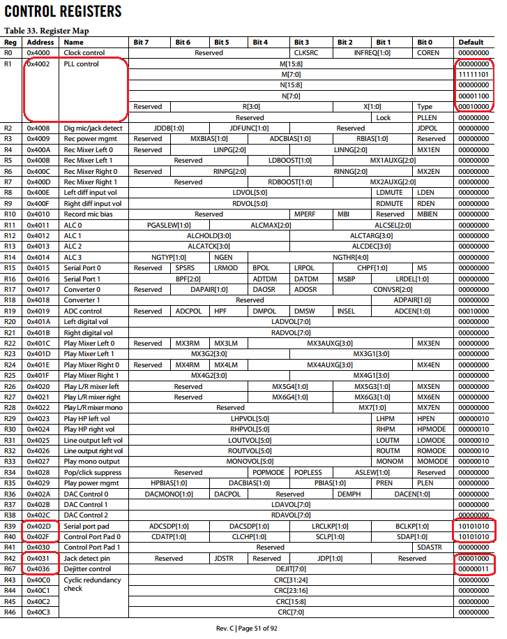
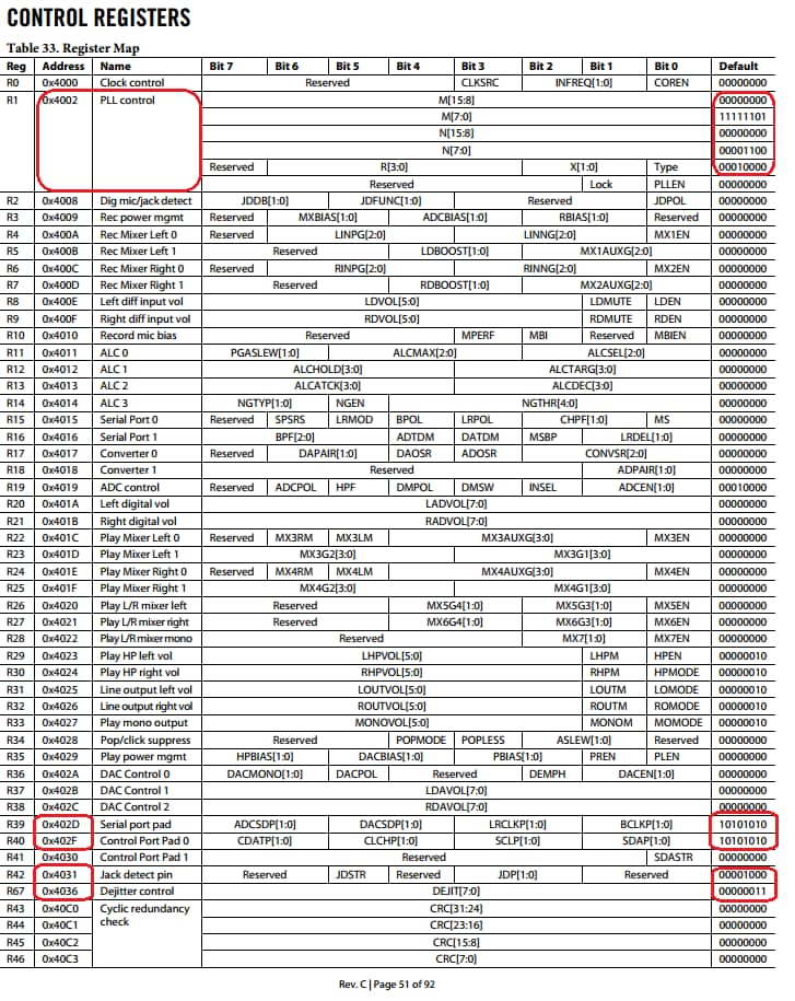
I took a look into your issue, and it seems that on power-up initialization of the ADAU1761, you need to program the Clock Control and PLL control registers before you can read back any other I2S register address. We do not have an ID register for the ADAU1761, however there are certain control registers which out of reset contain default values. Refer to Table 33 in the datasheet (shown below).
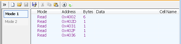
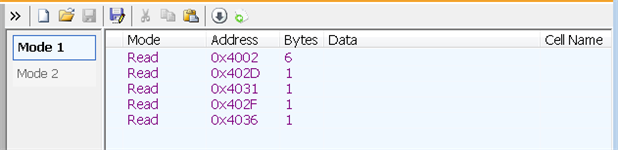
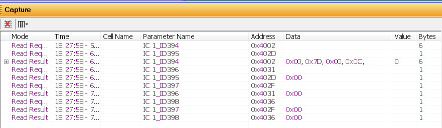
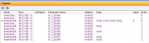
I could replicate your issue by setting up a test in the sequencer window reading some of these default registers highlighted in red. To do this I open up SigmaStudio but do not download the application code. Then I read registers through the sequencer window. It seems that out of reset, the PLL register is the only one we can read.
Now if we execute a Clock Control and PLL program command:
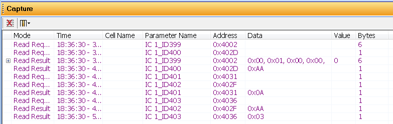
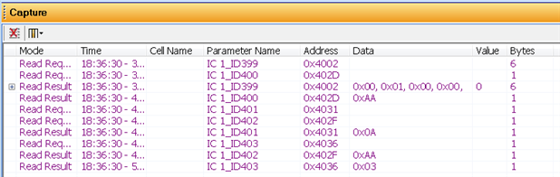
Next we go back and re-read back the same default registers to see if they agree with the Table 33 entries, and, voilà, we see the values are read back correctly!.
Here is a capture of register 0x402D (Serial Port Pad) Default is 0b10101010, or 0xAA, which is read back after programming the clock control and PLL registers.
Hope this helps!
-JT






Thanks John I was able to get it working finally by fully programming the device over i2c. It just took reading through some code and breaking out the logic analyzer. I had talked to support just before shutdown so I knew you guys were away. Thanks for taking the time to send a detailed explanation.
This question has been assumed as answered either offline via email or with a multi-part answer. This question has now been closed out. If you have an inquiry related to this topic please post a new question in the applicable product forum.
Thank you,
EZ Admin
Please log in to reply.