I2C address for ADAU1761
Hi
Could you please tell me, what is the I2c slave addresse of ADAU1761? Is it 0x70 or 0x38?
Thanks
Audio Signal Processors
SigmaDSP Audio Processors
adau1761
Hello Hossein,
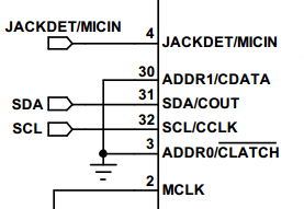
The address depends on how the ADDR0 and ADDR1 pins are hardwired per Table 21 in the datasheet:
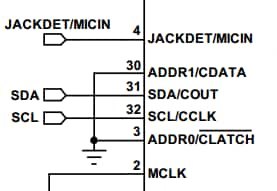
For the EVAL-ADAU1761 eval board, the default address is 0x70 (which assumes ADDR1 and ADDR0 are tied low).
-JT


Thank you John
Hi
According to table 21, Bit 1 is equal to one. it is possible that Bit 1 is equal to zero?


Hi
I have connected ADDR1 and ADDRo to GND, and I would like to write to some dsp registers. It means that the address of DSP might be 0x70.
I get NACK when I am using 0x70 as dsp address, but the dsp is responsed when I used 0x38 as dsp address.
I am a bit confused! Could anyone tell me what is going on?
Thanks
Hi Hossein,
(This is an edit of my previous response, please disregard that one)
I apologize for the delay with the US Thanksgiving Holiday last week.
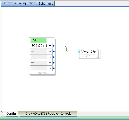
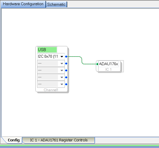
Table 21 described in the datasheet would need to be matched up to the HW configuration I2C address option in SigmaStudio when you to connect the USBi to the target.
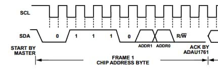
To verify, I connected up a logic analyzer to the USBi's I2C signals connected to the EVAL-ADAU1x61 eval board and also see address "0x38" is read/interpreted by the logic analyzer. However, if you look closely, you will see that the address byte data relative to the I2C clocks is 0 1 1 1 0 0 0 0 for I2C writes, which matches table 23 and figure 49 in the datasheet.
Can you verify the I2C data on the bus to make sure it matches this format as 0x70 (for a device with ADDR0 and ADDR1 tied to ground)? Perhaps it could be that your particular microcontroller interprets the I2C address byte as 0x38 (shifted then 1 bit to the left) and combined with the read/write bit "0" prior to transmitting the data to the ADAU1761? My analyzer seems to remove the R/_W bit and display the address as 0x38, but the data on the bus is displayed as 0x70.
-JT



Hi John
I hope you had a very happy thanksgiving holiday.
Thank you for the explanation. I will take a look into my microcontroller datasheed.
Br
Hossein
Please log in to reply.