Concerning RIAA CURVE of Phono amp in ADAU1761
Hi There,
I am using one of your product SigmaDSP(ADAU1761 Evaluation Boards).
I am also using applied program SigmaSudio 3.7 as well.
I would like to try RIAA CURVE of Phono Amp in the SigmaStudio.
I think it would be possible by using filter
but there are too many kinds of filters and a bit confusing how much I can put it on.
It would be appreciated if you could let me know how I can make it.
Best regards,
Honggi
Audio Signal Processors
SigmaDSP Audio Processors
adau1761
Hi Honggi,
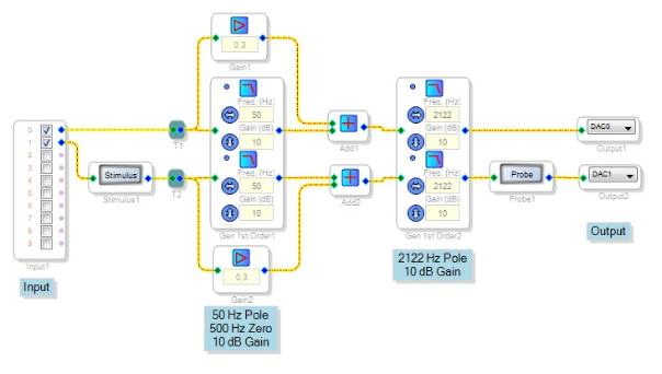
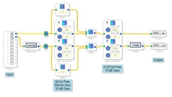
The RIAA playback curve starts with a first-order drop (pole) at 50 Hz, which begins to flatten out (a zero) at 500 Hz. Finally, another first-order drop at 2122 Hz completes the curve. Accomplish this with first-order low-pass filters, as shown below:
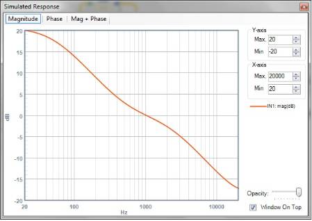
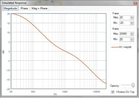
Find the filters under Toolbox/Filters/First Order/General (First Order). The first filter produces the 50 Hz transition. The response of this filter drops with frequency until at 500 Hz, the fixed gain block has more output than the filter -- establishing the second transition point where the curve flattens. The second low-pass filter resumes the slope at 2122 Hz. Embedded gains establish the overall unity gain at 1000 Hz. Compare the simulated response below with that shown under RIAA equalization in Wikipedia.
I gave this project a quick test by playing some music first through a EQ set to approximate the inverse (recording) curve, then through this project. It sounds OK to me.
Best regards,
Bob
Thank-you Bob!
I was planning to do this for one of my restored valve amps and a Garrard changer.
Now, I'll just use yours (If you don't mind).
Very simplistically and creatively done!!
Thanks again!!
Viva vinyl! And tubes!
Bob
Thank you very much for the detailed explanation.
Filter configuration was that I can not think of.
I am very pleased with the results.
Thank you.
Honggi.
Hello Bob,
Would the S/N ratio be affected if this is implemented in ADAU1701?
Thanks in advance!
Hi KKSL,
Since the playback EQ boosts the bass and reduces the highs, likely the best place for it would be in the analog reconstruction filter after the ADAU1701. Yet, placing it inside the -1701 simplifies the overall design and could actually be an improvement over the EQ's usual spot in the phono preamp. This way the ADAU1701's ADC sees less of the input's bass peaks, allowing for more input gain. It would also allow any advanced processing (see ADAU1701 RIAA ) to see the groove signal as opposed to the equalized version. Where I work we built a microphone mixer with ADAU1701's and for awhile were considering adding pre-emphasis in the mic preamps, then a treble cut filter in the DSPs to help kill A/D noise (which is the main limitation on the -1701's dynamic range).
Best regards,
Bob
Thank you for the input Bob.
I have one concern: If I interface the phono transducer directly to the ADC, will my resolution suffer, since the ADC will only see mv input as against the full input of ADC of 1V?
If so, then ADAU1761 would be a better choice since it has a 37db PGA built-in.
Thanks in advance!!
Hi,
You're absolutely right about a poor resolution / noise floor should you just tie a typical magnetic phono cartridge directly into a ADAU1701's ADC. I'd recommend that you precede the -1701 with an un-equalized preamp (like the SSM2019N). Or go with the -1761 as you suggested (I didn't notice that this thread actually references -1761, and I had assumed your input was already at "preamp" level).
The ADAU1701's ADCs are actually current-sensitive, with a FS of 100 uA RMS -- with the recommended 18K series resistor plus 2K internal resistance, this works out to 2V RMS full scale. The data sheet says:
The stereo audio ADCs are current input; therefore, a voltage-to-current resistor is required on the inputs. This means that the voltage level of the input signals to the system can be set to any level; only the input resistors need to be scaled to provide the proper full-scale current input. The ADC0 and ADC1 input pins, as well as ADC_RES, have an internal 2 kΩ resistor for ESD protection. The voltage seen directly on the ADC input pins is the 1.5 V common mode.
This suggests that the ADC input resistors are free choice, although I'm not certain of their acceptable range. For example, you could eliminate the 18K series resistor and go with only the built-in 2K resistance to get 20 dB more gain -- but this may still not be enough gain for your application. Also, come to think of it, phonograph cartridges are specified at a 47K load impedance so this idea won't work anyhow. Am I dating myself or what!
The ADAU1761 with its PGA could very well be a better choice. It's also low-power and can run a few more instructions, though you'll need a uC to boot it. I haven't designed with it except for using its eval board for testing my EZ suggestions, thus I can only suggest carefully matching its datasheet specs to your intended application.
Finally -- if I'm not mistaken, magnetic cartridges typically output a few mV RMS. Yet, I remember phono preamps boasting input overload ratings of 100 mV or more. I don't know if such is important, or is merely typical audio overkill.
Best regards,
Bob
Thank you Bob! The topic is now very clear to me.
Regards!
Please log in to reply.