about the PLL fractional mode in ADAU1361
Hi,guys,
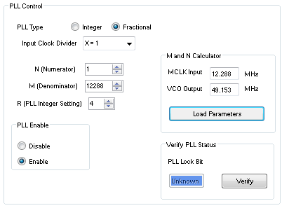
I'm now using ADAU1361 eval board , and SigmaStudio 3.6. And I found that if PLL fractional mode is used, and that fractional part value is too small(i.e. 0.0001), the PLL could not lock. See attached the picture. The oscillator on eval board is 12.288MHz, and I set VCO output to 49.153MHz purposely (actually it should be 48K*1024=49.152MHz),then PLL falls into unlock.
I could not find any restriction about PLL fractional mode. And could you give some suggestion about this?
Thank you.
adau1361
Integrated/Special Purpose A/D Converters
pll
Audio CODECs
I'm sorry it took me so long to address this issue. I recently took over responsibility for supporting the ADAU1361 from another engineer who left our group, so I am still getting up to speed.
I first checked the settings for your use case:
I verified the calculation 12.288 MHz / 1 * (4 + 1/12288) = 49.153 MHz. So, everything looks good.
I then went through my email archive to search for any comments regarding the ADAU1361's PLL, and I found the following information regarding a recent support case with another customer:
I had a look at this during the afternoon. I was seeing the behavior they describe with a jittery LR clock. If I changed the VCO output to just below 49.152 Mhz to 49.15 Mhz the jitter went away, and had negligible effect on the LR clock output rate. So it looks like it’s related to very specific N/M values. In other datasheets that I believe have the same PLL I have seen notes that state the ratio of N/M should be between 0.1 and 0.9 for optimal PLL operation. In their setup the ratio is 0.913, slightly above the recommended range.
So, it looks like the N/M ratio is supposed to be limited to the range of 0.1 to 0.9, but this information has not been put into the datasheet. In your use case, the N/M ratio is 0.00008, which is well below the lower limit of 0.1, so it seems like this is causing the PLL to not function properly.
After reading further, I found this information:
The issue is that the divide N/M ratio is too high 0.913 for the sigma delta modulator to operate correctly. Can they tolerate an LR clock that is slightly off 48Khz in their application? If so they could set the VCO output to 49Mhz and they will get an output LR clock 0f 47.85Khz. In this case the N/M divide ratio is 17/19 = 0.895, slightly below 0.9.
So, this really makes me believe that the limitation existing with the PLL (i.e. N/M must be between 0.1 and 0.9) was not properly documented in the datasheet. I will immediately request a datasheet update from our datasheet group.
I apologize if this has caused problems with your system design.
Please log in to reply.