How do I create a filter in SigmaStudio that is not part of the standard library?
How do I create a filter in SigmaStudio that is not part of the standard library?
filter
sigmastudio
SigmaDSP
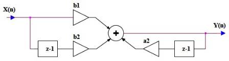
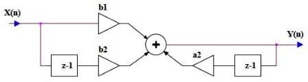
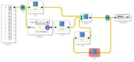
It’s possible to create your own digital filter architectures using the low-level add, multiply, and delay blocks in the SigmaStudio library. This might be the best solution since the filters you are looking to use are not part of the standard library. For example…
This…
Becomes this:
It is certainly more time consuming to design filters this way as opposed to the existing filters in our library, but it will afford you the flexibility to implement any architecture you wish.
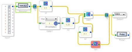
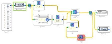
The cool thing is that you can even use the probe and stimulus functionality to check the frequency and phase responses.
Here is the schematic with probe/stimulus inserted:
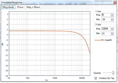
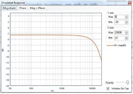
And here is the response:
So, if you can get the basic block diagram of the filter you want to implement, it’s pretty easy to connect some blocks and create it in SigmaStudio.

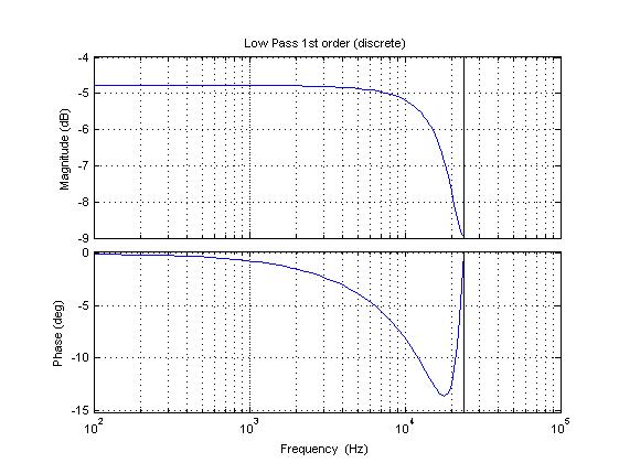
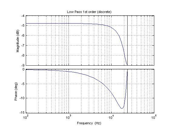
I've simulated it with matlab, here the code:
Fs = 48000; % [Hz]
Ts = 1/Fs; % [s]
z = tf('z',Ts); % discrete transform
b0 = 0.5;
b1 = 0.25;
a1 = 0.3;
tf1z = (b0+b1*(z^-1))/(1+(a1*(z^-1)));
figure(1);
bode(tf1z);
title('Low Pass 1st order (discrete)');
However bode seems to be a little different from probe window, I'm referring to gain error.
See image
Hello,
I'm afraid Brett is no longer on the forum (his dimmed avatar is your clue). The Stimulus-Probe tool only estimates the response of the feed-forward portion of discrete filters. It doesn't know how to handle Feedback blocks, so "homemade" IIR filters cannot be accurately estimated -- see https://ez.analog.com/message/120089#120089
Best regards,
Bob
Please log in to reply.