SigmaDSP ADC and DAC full-scale levels and signal scaling
Here's a question I received from an anonymous customer:
Why does it seem that I can never really get a truly expected output...even for the simplest setup [ADC in, DSP through, DAC out]? Not really a big deal for audio...but I'm wondering what I'm missing or not seeing here.
For instance, for the project file below, I put about 1Vpp in and even though there is no reduction set in the input or output settings in SigmaStudio, there is a signal reduction. Maybe there is something in my setup causing this.
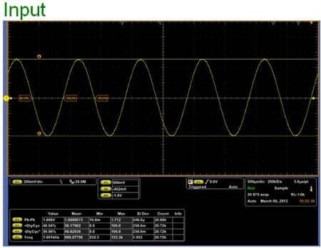
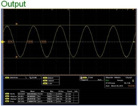
Scope shots of Input Pin 3 (LAUX) and Output (LHP) below.
1.008 V peak-to-peak
954 mV peak-to-peak
Audio Signal Processors
adc
SigmaDSP Audio Processors
adau1761
SigmaDSP
full-scale
dac
Show More
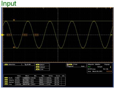
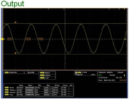
The reason that the levels are different is because the converters have different reference levels, commonly referred to as full-scale levels. Full-scale reference levels are often different between the ADC and DAC of a chip because they are set in a way that maximizes the performance of the converter designs, with regards to noise and distortion. In other words, we can gain a little extra performance by setting the ADC and DAC full-scale levels independently. You can find these full-scale levels in the datasheet.
The single ended inputs for the ADAU1761 are 2.83 V peak-to-peak for AVDD = 3.3 V:
However, the line outputs for the ADAU1761 are 2.60 V peak-to-peak for AVDD = 3.3 V:
Therefore, you get a linear scaling of roughly 0.92, or a reduction of 8%, when passing a signal from the input to the outputs.
You’re seeing about a 6% reduction in level. The 2% discrepancy between the datasheet and your results is because there are small variations in each piece of silicon during manufacturing that causes the levels to be slightly skewed in either direction. This is typically known as "manufacturing tolerance".




This question has been closed by the EZ team and is assumed answered.
Please log in to reply.