Load IIR Coefficients from internal calculation
I have a board with an ADAU1761 and an 8051 micro, and am trying to make the HPF and LPF with a variable frequency. At the moment the micro is pulling the sin(w0) and cos(w0) results from an external PROM and writing it to an interface read in the ADAU1761. The ADAU1761 performs the rest of the math to generate the IIR coefficients. Currently the micro reads these coefficients via an interface write and then safeloads them back into a Double Precision General IIR Coefficient Filter.
I'm trying to reduce the load on the micro.
Is there a way to have an arithmetic operation load directly into an IIR filter?
Thanks,
Ian
Audio Signal Processors
filter
SigmaDSP Audio Processors
adau1761
iir
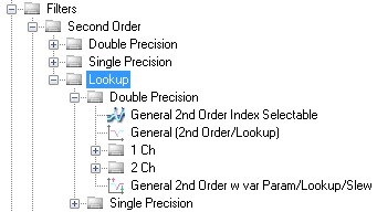
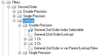
Depending on the range of control you wish to give the user, one option might be to store a table of filter coefficients in the SigmaDSP and simply let the user select from a number of options. You can do this by selecting filters from the "Lookup" subfolders in SigmaStudio.
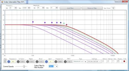
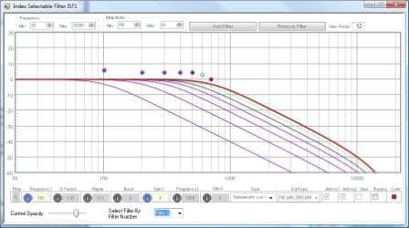
Here's an example of how you can add multiple filters for the cell, which are selected via an index input. The microcontroller writes a single index number to the SigmaDSP to select each filter.
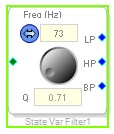
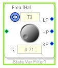
You could also try the state variable filter, which allows you to generate HP, BP, and LP filters from a single cell. The micro only needs to write the cutoff frequency and Q, and the filter coefficients are calculated internally.
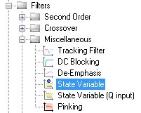
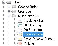
I started off trying the lookup method, but at the time I was getting pop/clicks when I changed the index. Granted this was the first day that I had an eval board and not have revisited since I’ve got more familiar with Sigmastudio.
The State Variable is probably a better solution, but a State Variable with Frequency Input would be perfect. This seems like would be simple variation of the current filters. Is there any way to build this?
Ian
The current State Variable Filter does have a frequency input. It's a single address in parameter RAM. There is, of course, a conversion required to calculate the value that needs to be written into RAM, but it's pretty straightforward. Your microcontroller would simply need to write that one address. Does that answer your question?
It answers the question as best it can be answered within the limitations of the SigmaStudio.
On a side note, I’m not sure why SigmaStudio is based around Sliders and GUI controls. While this does make testing and prototyping very easy, wouldn’t it be more functional for end user applications it these parameters could be inputs to the blocks (like the Q in the State Variable)?
Thanks, Ian
Hi Ian,
The SigmaDSP core is very streamlined for processing audio and the hardware design strives to be as efficient as possible with no overhead. Therefore, in the interest of obtaining the highest processing efficiency possible (think in terms of filters per program instruction), it is best to store the filter coefficients in the RAM directly as they are used in the multiply-accumulator.
If the SigmaDSP instead took values like Q, boost, and center frequency in its RAM and then had to manually calculate the IIR filter coefficients on its own, it would have to use its own DSP core (and program RAM... and paramter RAM!) to do the calculations, so the number of instructions per filter would increase dramatically.
That's the basic thought process behind designing the cells as they are. Let me know if you have other questions!
Doesn't the current State Variable filter do exactly that? By supplying the center frequency & Q to the RAM address the SigmaDSP does the work to implement the filter. I'm not sure how bringing this to a "pin" is any different. It would open up the possibility to modulate the center frequency of the filter by a LFO or a peak detector...
The tracking filter does this, but looking at the compilation capture window there is something more going on. Here it looks like the coefficients are actually being calculated.
It’s the same idea with the general IIR filter. Bringing the coefficient inputs to pins would at least give the designers an opportunity to implement an algorithm to generate the coefficients. It may not be as efficient as pre-calculating them, but opens the system up for other implementations.
Thank you for your support. It is greatly appreciated.
Ian
Hi Ian,
Yes, the state variable filter is particularly handy in this kind of application because its architecture allows a very simple internal calculation - scaling, essentially - to be the only SigmaDSP-side calculation required to convert the human-understandable concepts of Q and frequency to usable calculation coefficients.
However, standard IIR filters are a different story. Each parameter requires a significant number of additions and multiplications, which are not so DSP-intensive, but additionally need exponent and division calculations, which are extremely inefficient on our DSP hardware. Here's an example of the calculations required for a basic IIR parametric filter:
Ax = 10(boost / 40)
omega = 2 * PI * frequency / Fs
sn = Sin(omega)
cs = Cos(omega)
alpha = sn / (2 * (Q))
a0 = 1 + (alpha / Ax)
A1 = -( 2 * cs) / a0
A2 = (1 - (alpha / Ax)) / a0
gainlinear = 10(gain / 20) / a0
B0 = (1 + (alpha * Ax)) * gainlinear
B1 = -( 2 * cs) * gainlinear
B2 = (1 - (alpha * Ax)) * gainlinear
So, bringing out parameters like frequency and Q to input pins would be impractical.
However, I do see your point about the option of creating 5 input pins, one for each of the IIR coefficients. I will suggest this possibility to the software team.
You would still have to divide all of the coefficents by a0... Yeah, I have most of that working. It's not clean, but it works.
Now that you pointed out the ease of the state variable filter I'm heading that direction instead. A pin for the frequency would be very useful. I see why there is a Q input version since the SigmaDSP only requires 1/Q conversion while the frequency input would need to go through the f0*2*pi/fs. Now I'm doing this conversion in the SigmaDSP through separate interface read/write step before safewriting it back to the State Variable RAM address.
A variation of the State Variable that eliminated the micro involvement would be really convenient.
Anyway, Thanks for the help.
Ian
This question has been closed by the EZ team and is assumed answered.
Please log in to reply.