SigmaStudio for ADAU1761, Phase shift of +- 45° ?
Hello,
How would you implement a phase shift of plus or minus 45 degree of your signal ?
My signal is not a constant frequency, but voice at 100-2700 Hz.
With an all pass FIR ?
With sin and cos functions, which I do not find in the software?
Thanks for the help, very appreciated!
Dany
Audio Signal Processors
SigmaDSP Audio Processors
adau1761
Hi Dany,
In general, rather than +-45 degree phase shifts, you could implement the phase shifter as a pair of low-pass filters, one with a 90 degree phas eshift in its output.
I'm not sure what's currently available in the SigmaStudio instruction set so please stand by while I bring in a ringer, er, software expert.
A colleague and I did a SDR design for a customer using one of the SigmaStudio parts, which provided baseband gain and filtering and of course high resolution, low poaer ADCs. Its I and Q digital outputs drove one of our Blackfin processors, which in turn provided timing recovery, frequency control, demodulation, and of course also controlled the radio.
I did the radio and analog baseband design, he did the digital baseband and signal processing, and we collaborated on the power supply.
More to come!
Regards,
Bob
Hi Dany,
Bob asked me to jump in here. Seeing as this is a software radio forum, I'll answer it first in terms of a software radio, but I'm suspecting that you are really asking about an audio application that may define phase shifts a little differently. If so, you may want to redirect your post to the SigmaDSP forum.
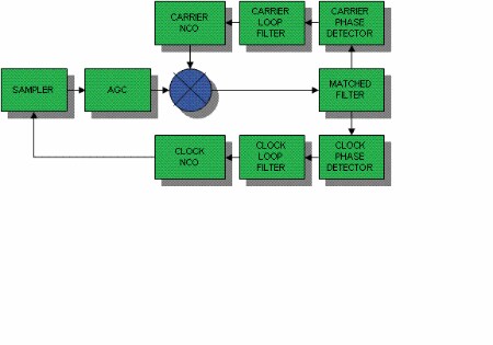
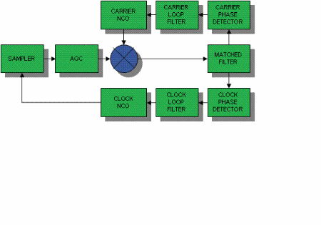
In software radio applications, when we talk about phase shifts we are usually concerned with centering an incoming signal constellation at baseband. An example of this would be centering an incoming QAM signal so it is at zero frequency (no rotation) and zero phase (lined up with the X and Y axis). Frequency and phase shifts such as these are most easily accomplished using a complex mixer (the blue circle in the diagram below) and NCO combination. The C code for complex mixer looks like ...
mixerOutI = (mixerIn1I * mixerIn2I) + (mixerIn1Q * mixerIn2Q);
mixerOutQ = (mixerIn1Q * mixerIn2I) - (mixerIn1I * mixerIn2Q);
where the mixer inputs are the signal and the output of an NCO (the digital equivilent of a VCO). The NCO outputs look like this ...
mixerIn2I = cos(2*pi*N*frequency + phase)
mixerIn2Q = sin(2*pi*N*frequency + phase)
In your case the frequency offset is zero so you are only left with the phase term.
For 45 degrees ...
mixerIn2I =cos(pi/4) = .707
mixerIn2Q =sin(pi/4) = .707
For -45 degrees ...
mixerIn2I =cos(-pi/4) = .707
mixerIn2Q =sin(-pi/4) = -.707
Best regards,
Kevin
By the way, here is the link to the SigmaDSP forum if you need it ...
Hello Bob and Kevin,
First, many thanks for the effort of researching and writing on the subject!
I am on the right thread, and I really want to talk about SDR!
A + - 45° phase shift, to add or subtract to the I and Q signals is the aswer, and the sin/cos of 45° is a know value.
Case solved, actually by a much simpler solution than I thought at first
I will leave it there. Thanks for the effort.
Please log in to reply.