Phase shift on prototype with ADAU1446 and TI PCM3168
A customer contacted me regarding a phase shift seen on a board using the ADAU1446 and a TI PCM3168 codec. I will try to investigate the cause of this and post my results here.
Audio Signal Processors
phase_shift
adau1446
SigmaDSP Audio Processors
SigmaDSP
phase
Show More
Hi Brett,
Please review attached document.
Thanks.
Hello,
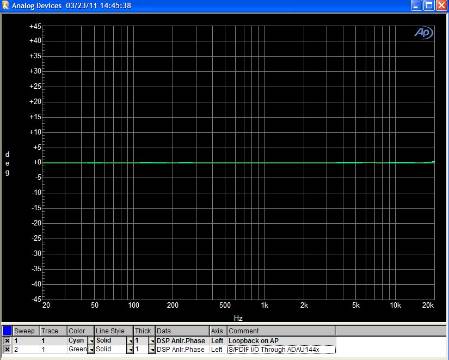
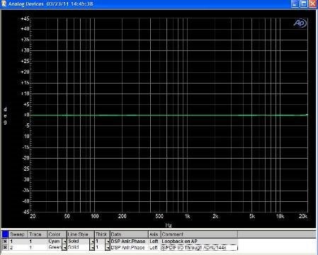
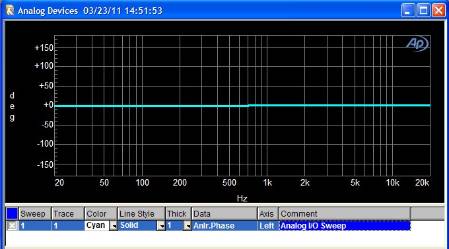
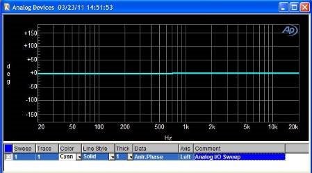
I tested this today in the lab and I was unable to duplicate your results. I started by doing a simple input/output loopback test on my AP as a sanity check. This gave me the expected 0 degree phase difference across the entire frequency range. Then I tried using the S/PDIF input through the ADAU144x's ASRC and routing it digitall out through the S/PDIF transmitter (i.e. and all-digital path). Again this gave me almost 0 degree phase shift across the spectrum. Finally I tried routing the audio in analog through the AD1938 - ADAU144x - AD1938 path, to check if the converters played a role. Again, I got almost no phase shift. So, it looks like the AD1938 and ADAU144x are not affecting the phase response at all. Please check with TI to see if their PCM3168 might be causing the issue.
My AP plots are attached for your reference.
Hello
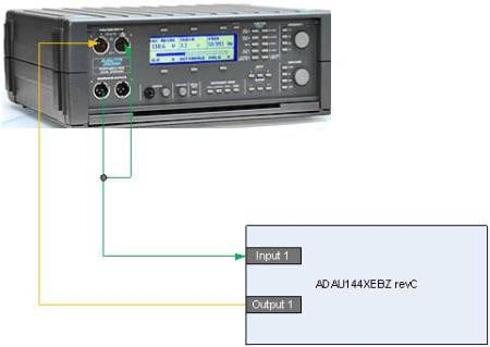
Today I was able to get the ADAU144x evaluation board.
I created very simple project: input connected to output. (Project attached).
After that I connected my AP portable One Plus audio analyzer and checked phase deviation.
To test phase I used internal generator as a reference. Before making my measurements, I tested my loopback setup by connecting in-out cables and I get 0 deg phase shift sweep.
I got almost the same phase plot, I e-mailed to you earlier.
When I used dScope Series III from prism sound, I had the same 180 degrees phase rotation.
After this test I am thinking that the only common part between our design and eval board is 1446 DSP.
Hello Brett,
I tested the phase shift on 1446 eval board and our new design board again.
I used different AP audio analyzer and got the same saw tooth phase swing.
After that I used 2 channel scope to see input/output phase difference and I could observe the phase shift vs frequency. I illuminated input output filters by testing them separately.
Also I take of the shelf BIAMP NEXIA DSP based mixer and make the same testing.
All tests come out almost the same. Do you have any idea what is going on?
Thank you,
Mark Naiditch
From: BrettG analog@sgaur.hosted.jivesoftware.com
Sent: Wednesday, March 23, 2011 3:00 PM
To: Mark Naiditch
Subject: New message: "Phase shift on prototype with ADAU1446 and TI PCM3168"
Analog Devices EngineerZone <https://ez.analog.com/index.jspa>;
Phase shift on prototype with ADAU1446 and TI PCM3168
reply from BrettG <https://ez.analog.com/people/BrettG>; in SigmaDSP Processors - View the full discussion <https://ez.analog.com/message/21643#21643
The ADAU1446 does have a group delay, which means that all frequencies are delayed by a certain, fixed amount. This is different from phase delay, meaning different frequencies are delayed by a different amount. In any case, I will try to send some sinusoidal pulses through the DSP and check the delay time. If the delay is equal for all sinusoid frequencies, then that should show that there is no phase shift caused by the DSP. I have been very busy lately, but I will try this today or on Monday if possible.
Hi Brett,
Please review my group delay measurement:
I applied 1KHz square wave and measured output delay. I increased input frequency by 100Hz and measured correlated output delay:
1KHz 30uS
1.1KHz 120uS - ∆=90uS
1.2KHz 200uS -∆=80uS
1.3KHz 260uS -∆=60uS
1.4KHz 312uS -∆=52uS
1.5KHz 362uS -∆=50uS
1.6KHz 404uS -∆=42uS
1.7KHz 442uS -∆=38uS
1.8KHz 474uS -∆=32uS
1.9KHz 504uS -∆=30uS
2.0 KHz 528uS -∆=24uS
Thank you,
Mark.
From: BrettG analog@sgaur.hosted.jivesoftware.com
Sent: Friday, April 01, 2011 12:49 PM
To: Mark Naiditch
Subject: New message: "Phase shift on prototype with ADAU1446 and TI PCM3168"
Analog Devices EngineerZone <https://ez.analog.com/index.jspa>;
Phase shift on prototype with ADAU1446 and TI PCM3168
reply from BrettG <https://ez.analog.com/people/BrettG>; in SigmaDSP Processors - View the full discussion <https://ez.analog.com/message/22237#22237
Hi Mark,
I still do not see the results you see. I tried a test today with the evaluation board using analog audio in/out. The path is AD1938 ADC - ADAU1442 - AD1938 DAC. I recorded the input on one channel and the output on the second channel. You can see from my three tests (1 kHz, 5 kHz, and 100 Hz) that at any frequency, the delay is always the same. The phase delay appears to be the same for all frequencies, and the group delay is always the exact same number of samples. Please see my attached results.
For each test, the input is on the right channel and the output is on the left channel.
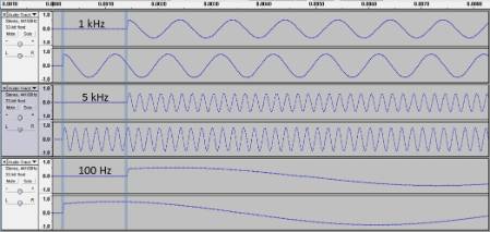
Mark, do you have any processing enabled in the DSP? Certain processing blocks like IIR filters have a non-linear phase response that could be contributing to this. All of my tests are with a bypass path in the DSP.
Brett,
I have input to output direct connect configuration.
Thanks,
Mark.
From: BrettG analog@sgaur.hosted.jivesoftware.com
Sent: Monday, April 04, 2011 10:52 AM
To: Mark Naiditch
Subject: New message: "Phase shift on prototype with ADAU1446 and TI PCM3168"
Analog Devices EngineerZone <https://ez.analog.com/index.jspa>;
Phase shift on prototype with ADAU1446 and TI PCM3168
reply from BrettG <https://ez.analog.com/people/BrettG>; in SigmaDSP Processors - View the full discussion <https://ez.analog.com/message/22286#22286
Hi Brett,
Please review my measurements:
The pink (bottom) trace is input signal and the blue (top)- output. DSP configuration: input connected to output.
1. Frequency 1KHz, Input output delay = 22uS.
image001.png
2. Frequency 1.25KHz, Input output delay = 226uS.
image002.png
3.Frequency 1.6KHz, Input output delay = 400uS.
image003.png
As you can see we have almost 180 degrees phase rotation between 1KHz and 1.6KHZ.
Thanks,
Mark.
From: BrettG analog@sgaur.hosted.jivesoftware.com
Sent: Monday, April 04, 2011 10:43 AM
To: Mark Naiditch
Subject: https://ez.analog.com/message/22343#22343/SigmaDSP Processors New message: "Phase shift on prototype with ADAU1446 and TI PCM3168" https://ez.analog.com/message/22343#22343/1NrpPa-a7h-5Nb
Analog Devices EngineerZone <https://ez.analog.com/index.jspa>;
Phase shift on prototype with ADAU1446 and TI PCM3168
reply from BrettG <> in SigmaDSP Processors - View the full discussion <https://ez.analog.com/message/22269#22269
Hi Mark,
This looks like a constant group delay, not a frequency-dependent phase delay. In order to really see what is going on, try this test:
Mix two sine tones together on the input. Perhaps you could use one tone at 1 kHz and one at 1.5 kHz. When you mix these tones together, you'll get a waveform that contains both components.
Now, measure the input and the output of the DSP. If the DSP has frequency-dependent phase delay, then you should see the shape of the waveform change, because each frequency component will be delayed by a different amount.
If the shape of the waveform does not change between input and output, that means that each frequency component is delayed by the same amount. That indicates that there is no phase shift, but rather a constant group delay (i.e. a shift in time that is the same for all frequencies).
I'm currently in a hotel on a business trip so I can't do this test on my own. Please try it out and let me know the results.
Hi Brett,
This is 1 and 1.7KHz multi burst . The pink trace – input and blue – output.
Pick to pick input timing is 622uS:
image001.png
And output is 498uS:
image002.png
Input output difference is 124uS.
Thank you,
Mark.
From: BrettG analog@sgaur.hosted.jivesoftware.com
Sent: Tuesday, April 05, 2011 5:35 PM
To: Mark Naiditch
Subject: https://ez.analog.com/message/22433#22433/SigmaDSP Processors New message: "Phase shift on prototype with ADAU1446 and TI PCM3168" https://ez.analog.com/message/22433#22433/W9xEu-a7h-5Pp
Analog Devices EngineerZone <https://ez.analog.com/index.jspa>;
Phase shift on prototype with ADAU1446 and TI PCM3168
reply from BrettG <https://ez.analog.com/people/BrettG>; in SigmaDSP Processors - View the full discussion <https://ez.analog.com/message/22407#22407
Hi Mark,
Thanks for running that test. Since I am traveling on business, I can't test this on my own until I return to the US. I will try this test next week - probably on Monday - and I will post my results.
Hi Brett,
why didn't you answer our question?
Hi Sir ,
When will he back to US office ? this is the last question for our project and very urgently .
Thanks for running that test. Since I am traveling on business, I can't test this on my own until I return to the US. I will try this test next week - probably on Monday - and I will post my results.
why didn't you answer our question?
I'm sure Brett appreciates you running the test, however, I believe he is currently traveling internationally on a business trip and wont' be able to do any analysis on your images until he returns to his office in the US. I'm sure when he gets back to his office (rumor has it's on Monday) that he will look it over and answer your question by posting his results.
I do not work at Analog Devices and I do not know Brett's schedule. However, after reading the post about him being out of town it was clear to me why he was unable to immediately respond with a thoughtful answer to your question.
Personally, I have been working a lot with an ADAU1442, ADAU1445 and ADAU6 using an AD1939 and have never seen a phase shift that was from the DSP and I doubt your problem is the PCM3168. Are you 100% it's not from an RC, RL or RLC circuit before and/or after the PCM3168? All DSPs and codec will cause delay in your signal, you can't get around that, but it should be tie domain only, not frequency. I believe your time is best spent looking elsewhere in your circuit or possibly the modules within your SigmaDSP, not the chip itself.
Hi Mark.
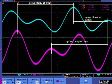
In all of your measurements, I don't see where is considered the group delay of the DSP. It is around a 1 ms, and is comparable to the period of 1-2 KHz signals. Just measuring the time to the nearby peak in input is wrong.
For example of your results:
1KHz 30uS - It is a group delay of 1030 us and 0 deg phase
1.4KHz 312uS - 1/1.4 = 714us + 312 = 1026 us (you make a error of 1 period and 312 us, which is near to 1030 us)
1.8KHz 474uS - 1/1.8 = 555us + 474 = 1029 us
2.0 KHz 528uS - 1/2.0 = 500us + 528 = 1028 us
Take a look always 1030 us ahead - there will be always signal with same phase.
Hi Svilen,
How would you explain my multi burst measurements, when I applied 1 and 1.7 KHz and observe input output phase difference?
Hi Mark.
It is in front of your eyes, just consider the group delay and look to the right portion of output signal:
Probably you right,
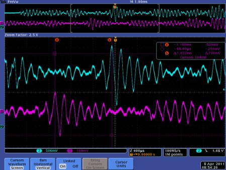
I checked this with complex wayform and got constant delay 1.032 mS.
Looks like I can’t use conventional audio analyzer fohttps://ez.analog.com/cfs-file/__key/communityserver-discussions-components-files/396/6e755e9269e0c2c8805eb7efc27af3b6.htmlr phase measurement.
Pink trace: Input
Blue trace: Output

Hi Mark,
I guess I should have suggested from the start that you test a complex waveform like that or a square wave (which has a ton of harmonic content). I guess this was a good learning experience for me, too!
Thanks for helping out, Svilen and MagicRub.
Best Regards from Frankfurt,
Brett
Thanks to everybody for excellent respond.
HI Brett,
You do not reply to my E-mail.
Best Regards,
Windy
This question has been closed by the EZ team and is assumed answered.
Please log in to reply.