Index selectable filtering issue
Hi guys,
I'm back with another issue on this. I actually posted this at the end of an old discussion, but wasn't sure if it'd be found!
My sub layout is shown below. Im trying to convert values from 0-1 to between 0-15, then use this value to control an ISF block. I'm at a bit of a loss as to whats wrong here, can you help? As far as I know, I'm controlling the ISF block with a 28.0 signal between 0 and 15, yet it doesnt seem to change and doesn't show up on the probe as changing.
Thanks,
Nick
Audio Signal Processors
sigmastudio
SigmaDSP Audio Processors
adau1701
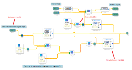
Sorry I had missed this post for a few days. In order to use any index-selectable block in SigmaStudio, first convert your control signal so that it ranges from 0 to 1 (in 5.23 format), and then multiply it by the number of indices (in 28.0 format). It looks like you're having no problem converting to a 5.23 value ranging from 0 to 1, but you're then multiplying by some value in 24.4, which I don't quite understand. Change that cell from 24.4 mode to 28.0 mode and then in the value box, enter the number of filters you have in your ISF cell. Then it should work as you want it to.
More information can be found in this application note, particularly in the Auxiliary ADC Slew Multiplexer section.
Hi Brett,
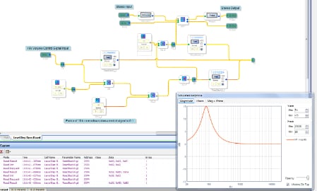
I've updated my layout to match your suggestions:
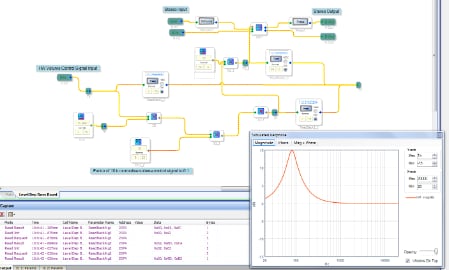
I can see from the readback block that it is rounding to the nearest filter index in 28.0 just before being sent to the ISF block, but still the probe window shows that it is selecting filter 0 and not changing based on the index control signal...
From changing the filter index by hand within the ISF window, i can see that the probe signal is updated to match the response of the ISF block, so I'm assuming that changing the filter index with a control signal should also updated the probe plot?
Thanks
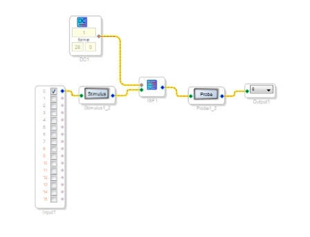
I just tried the simplest setup I could think of on a different board (1940 eval this time)
This is following the help file for the ISF block, and this still doesnt change the filter (when viewing the probe plot) yet if a new filter is selected manually within the ISF window then it changes...
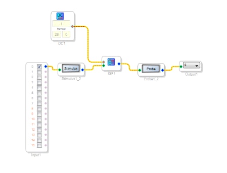
Hi Nick,
The probe/stimulus cells are intended as an offline tool. In other words, they will work regardless of whether or not an evaluation board is connected, or if the project is even compiled or not. Basically, they're meant to show the calculated (not simulated or measured) frequency response between two points in the signal flow. They are not capable of understanding many of the cells in the library, such as dynamics processors, because of the non-linear nature of those cells.
The stimulus/probe cells were basically intended for visualizing the overall response of multiple cascaded filter cells, since those cells don't generally have an interface that displays the response for you.
Because of the relatively simple coding of probe/stimulus to meet that goal, I believe it will simply select the most recently modified filter in the ISF cell. Unfortunately it is not smart enough to calculate that in real time as the input index changes.
Rest assured that if you actually listen to the audio output, you should hear the filters changing predictably when you modify the index.
I will submit an update request to the software team so that the stimulus/probe cells can more accurately handle the ISF cell. However, I believe that this will be treated, at least for the time being, with lower priority relative to more urgent update requests.
Hi Brett,
Unfortunately, the ISF block still isn't changing filter. It either doesnt work (filter) at all, causes no output at all or causes horrifically loud screeching...
I will attach my sub layout to an email to sigmadsp@analog.com, could you please sanity-check it for me?
Does the conversion between 5.23 and 28.0 not need some scaling factor of 2^23 (or 2^-23, cant remember which way round it is)? I've tried both and it allows signal to pass but doesnt change the filter value either.
Thanks,
Nick
Hi Nick,
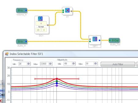
I'm having trouble seeing exactly what you want to accomplish here, so I decided to just attach a very simple example.
This example has 4 filters in the index-selectable filter cell. It has an analog control voltage that comes in on the "Volume_In" input, and this signal can range from zero to one in 5.23 format. I figured that you could easily test this with an auxiliary ADC, which has the range of zero to one in 5.23.
I then multiply that "Volume_In" signal by 4 in 28.0 format. This matches with the 4 indices in my ISF cell. This essentially maps the entire analog input range to 4 discrete values:
If the input signal is between 0 and 0.25, it will be mapped to index 0.
If the input signal is between 0.25 and 0.5, it will be mapped to index 1.
If the input signal is between 0.5 and 0.75, it will be mapped to index 2.
If the input signal is between 0.75 and 0.999999, it will be mapped to index 3.
In the extremely rare case that the input voltage actually hits full scale (i.e. one in 5.23 format), then it will output index 4. However, in practice our aux ADC inputs will probably not ever hit this max value. You could actually guard against any problems by inserting an index 4 filter in your ISF cell that is exactly equal to the index 3 filter.
This should effectively take your input signal and allow it to control which filter is selected in the ISF cell.
Note that you can increase the number of indices in the ISF cell to any number, as long as you also change the 28.0 value in the DC cell to match it.
If this doesn't answer your question, let me know and we can try again!
Hi Brett,
It was a bit of a schoolboy error on my part. I was converting to 1-16 before going to 28.0, therefore ended up with a 16x16 multiplication, rather than 1x16...
Thanks for your help!
Hi BrettG,
I'm new to sigma studio so I'm not so familiar with all the components. Can you explain how to get an analog control voltage? Can I use a peak envelope to transfer the input into dc signal and then use it to map from a LUT?
Thanks,
Joseph
Please log in to reply.