ADAU1761 MidEQ and Level Detector Designer
Hello all,
I've been playing with the ADAU1761 for a little while and am having quite a bit of success, but I've run into a couple of things that have stumped me. I'm using the ADAU1761 eval board and the EVAL-ADUSB2Z usb to I2C board with SigmaStudio 3.1. Right now I have a project that takes Audio in -> Medium Size EQ (grown to 15 elements) -> Tee with one branch to DAC output, other branch to Single Volume Control (set to 20 dB gain) -> Pass Through Level Detector Designer (grown to 14 elements). With this setup everything works great in sigma studio.
Now I'm ready to move it a microcontroller for control, but I can't make sense of how to calculate the values to be programmed to the MidEQ when I want to change one band's gain. I found the register locations in the *PARAM.h file, I can't find any documentation on how calculate the values to program if I want -5dB or 10dB on any given band.
The next thing I can't figure out: While running the project in sigma studio, the display of the 14 element Level Detector updates beautifully with the audio. However, I can't figure out what address is SigmaStudio reading that information back from. I would like my microcontroller to pull that data to be used by my application. I tried using the RTA level detector with 14 DSP readback blocks instead, but the blocks all read back as zero in SigmaStudio.
Anyone have any ideas?
Audio Signal Processors
SigmaDSP Audio Processors
adau1761
For filter calculation, please see this post:
https://ez.analog.com/message/5485#5485
The level detector is a bit of a different story. This level detector functions by basically reading back the instantaneous audio signal levels in the core and doing the RTA processing inside your PC. There is no RTA processing done inside the SigmaDSP. So, in order for this to work in your project, you'll need to emulate the RTA processing in the SigmaDSP. You will need to use the DSP Readback cell instead of the Level Detector cell.
For information about the DSP readback cell, please see this post:
https://ez.analog.com/message/7669#7669
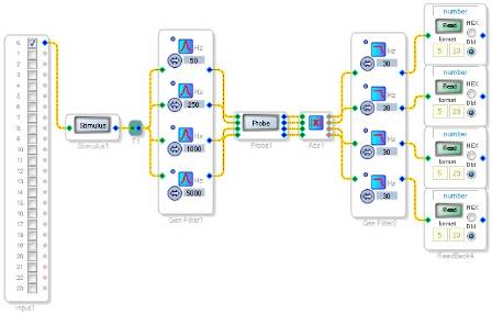
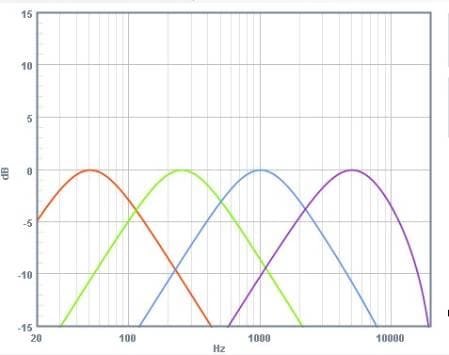
In order to implement a basic multi-band level detector, I'd recommend using the ABS - LPF method, which gives an approximate running average of the signal. You can use SigmaStudio's bandpass filters to create your level detector crossover and follow it with absolute value, LPF, and readback cells. I created a sample project including a 4-band level readback section. The project file is attached.

Thanks! I was able to take your suggestion and adapt it to my needs perfectly. It's even less resource intensive now.
A note to others looking to use the MidEQ but not store a bunch of filter coefficients in your design. I found that instead of using a MidEQ to do equalization, I used 2 banks of "General 2nd Order" filters (one for left audio, one for right audio) followed by a single bank of Stereo Mixers. The General 2nd Order filters are all configured as band pass, and the Stereo Mixers adjust the level of each band and mix it down to a single Stereo signal. So instead of writing coefficients you just write volume settings for each band. That is basically how I thought that the MidEQ worked. Once I learned that wasn't the case, I went ahead and made what I wanted.
Good idea, Tim.
In order to implement an EQ that is not coefficient-intensive, your idea to use linear gain on bandpass filters works very well.
That is, in essence, the same architecture as a graphic equalizer.
This question has been closed by the EZ team and is assumed answered.
Please log in to reply.