ADAU1466Z Sample Rate Conversion
I'm working on a project involving SigmaStudio and EVAL-ADAU1466Z dev kits, and I'm having problems with sample rate conversion. I have the board set to the default sample rate of 48 kHz; what I'd like to do is upsample to 192 kHz, delay, and then downsample back to 48 kHz in order to implement shorter delay increments than the ~20 us associated with a single sample at 48 kHz. Whenever I try to do this, I get compilation errors. I've made a simple testbed project that does nothing other that upsample 2x, then downsample 2x, and I still get the compilation errors, so I feel fairly confident that the errors are related to the upsample/downsample blocks.
Here's the compiler output:
##### Compile Started: Tuesday, March 5, 2019 4:17:16 PM #####
error (314,Beginning): The name 'MP1_DM0' in memory 'DM0' is undefined (319)
error (315,Beginning): The name 'MP1_DM0' in memory 'DM0' is undefined (320)
error (319,Beginning): The name 'MP1_DM1' in memory 'DM0' is undefined (324)
error (320,Beginning): The name 'MP1_DM1' in memory 'DM0' is undefined (325)
error (324,Beginning): The name 'MP1_DM1' in memory 'DM0' is undefined (329)
error (325,Beginning): The name 'MP1_DM1' in memory 'DM0' is undefined (330)
Does anyone have any guidance on how to properly implement the upsample and downsample blocks?
Audio Signal Processors
sample rate
SigmaDSP Audio Processors
delay
sample_rate
adau1466
Show More
Hello rg1,
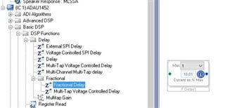
There is a bug with the upsample and downsample cells that will be fixed in the next revision. Now, people usually do not upsample since that is somewhat wasteful of MIPS. There is a better solution to your basic challenge of getting finer resolution.
You can use the fractional delay cell to obtain a delay value that is between sample periods. There is one that is voltage controlled and one that you have to put in the value. This can be done with a controller if you have on in your system. Here is where you find it:
Now I should mention that there was a bug with the external voltage controlled cell that I reported and they fixed but I am not certain if it is in Rev 4.2 or if it also will be in Rev 4.3. The bug was that the delay input was not from 0 to 1 for no delay to 100% full delay, It was from -1 to +1 so when you put in a zero you have a delay time of 50% of the max. If you need to do that let me know, I did work up an example on how to work around that. I think it may be up on the forum.
Dave T
Dave,
Thanks for the prompt and helpful reply! This should help me do exactly what I need to do.
Please log in to reply.