Completely powering off or power reduction modes of ADAU1761 to save battery consumption
Dear community,
We're having a bit of a hard time figuring out what is the best way to get into a sort of deep-sleep-like mode with the ADAU1761.
The goal is to consume as little as possible when the user is not actively using the device/ listening to music, to save battery time.
In the ADAU1761 datasheet on page 24 it suggests some power reduction modes, but to our best understanding:
- non of these modes reduces the consumption dramatically (although we could easily be wrong), and,
- our battery will still run out in a matter of days rather than weeks or more (preferably).
We set out to try and turn off the DSP entirely and turn on again, but that causes our microcontroller to reset repeatedly. It's not clear why but we suspect it's caused by the i2c lines becoming suspended/ stuck between the microcontroller and the ADAU and the microcontroller not being able to read/write on the ADAU anymore.
Any genius ideas out here we could try?
DaveThib we need your super help
Cheers!
Audio Signal Processors
hardware
sigmaStudio 4.7
sigmastudio
SigmaDSP Audio Processors
adau1761
Show More
Hello Orpheus,
Any of the power saving modes were meant to only save a small amount of power to increase battery life while using the part and the extension would be measured in minutes or perhaps an hour or so. This part is getting a little older so it is not designed with a very low power process like our newer parts are.
The other frustrating thing with this part is that it does not have a register to hold it in reset. Then to make matters worse it does not even have a reset pin!!
So if you want power saving to be days then you need to gate the power to the device. Power it down fully.
The issue you ran into is that you HAVE to isolate the codec from any signal, analog or digital, that is still active by using level translators. That will isolate the two power domains. They do exist for I2C lines as well. You are correct that powering down the part will pull down the I2C lines and hang up the bus.
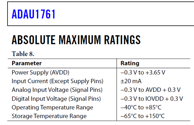
Note in the Absolute Max section of the data sheet.
Max on the analog pins is AVDD +0.3V and for the digital pins it is IOVDD+0.3V
Well, when AVDD and IOVDD=0V, then the MAX for both is 0.3V. So anything above that will violate the max voltage and will forward bias the ESD diodes and attempt to power up the part via analog and digital pins. I have seen this actually keep a part alive or prevent the part from actually doing a reset when powered down while things like clocks are still applied.
So you can do this but you must look at every pin and determine if the signal is still there when the power is shut down on the codec.
Dave T
Dear DaveThib ,
Thanks for the constructive response, as always.
I've now talked with the different stakeholders about this problem, and to be fully honest with you, I don't think anyone fully understands the solution you're suggesting to implement. So I'll describe here what I think you're saying and please correct me if I'm wrong. Here we go.
From your experience, it has happened that even when AVDD and/or IOVDD = 0, the codec (when you say codec, I assume you mean the whole chip) can still remain powered ON because we're un-purposefully supplying that voltage via the analog and/or digital pins.
AS SUCH, what you are suggesting is that we GATE all the supply pins (AVDD, IOVDD), GATE all the active signal pins (analog, digital) and GATE the i2c digital lines (clock and data) using level translators. Is that correct? Probably not? If not, if would be fantastic if you can explain it in baby steps and assume that I know nothing (like John Snow).
Note: The supply going into the codec is currently 1.8V and the i2c lines connected to it are also coming from a microcontroller supplied with 1.8V Your suggestion of the level translators also got the stakeholders confused - why should a level translator be used if there's no voltage to translate? Hence our understanding that you're suggesting a level translator specifically for gating.
Have a great weekend!
Just chiming in as a user of these things. It's not (just) that the chip remains on, it's that the chip can be damaged if there are analog or digital signals outside of the acceptable range as published in the datasheet. With zero AVDD/IOVDD, it's imperative that no signals are imposed on the pins.
Level translators are a clever way to do this, as when off they convert the level to "zero". Personally, I just make IOVDD the same power net as my microcontroller's power, and the power consumption is still minimal. YMMV.
(Signed, someone who cooked plenty of chips many years ago overlooking this!)
Thanks for the 2 cents joe42 !
Any comments regarding my last questions or was that confusing DaveThib ? Cheers!
Hello Orpheus,
Baby steps.
To save the maximum power, you can power down the entire part. Use power FETS to shut off (gate) the power to the device. So when you shut it off it has no power. So the value of the power supply is now zero volts. At that point ANY signal above 0.3V will violate the maximum allowed voltage on any of the pins. So therefore, you have to deal with it by using level translators. As Joe42 says, it will be translating from 1.8V of your controller to 0V of the codec when the codec is powered off. the same goes for all the pins, and GPIO or analog as well. You can be careful and mute the audio. That would work just as well. Also look at all the clocks going to the codec. So it is a lot of work and parts to try to save a little power.
joe42 I do not think you would have been that careless to have blown up a number of chips, I think it was a friend who did that once, you know, wink-wink, a close friend once did that! LOL. Hey, it happens to all of us. A couple of years ago I blew up an ADAU1787 eval board on the bench when testing a compressor. I spaced that the Audio Precision test was defaulted to step the level from like -60dBu to +30dBu. Needless to say, the 1.8V powered device did not like +30 being fed into it! Oops! I did not get any smoke but it died nonetheless.
Back to the question at hand. Having a 3.3V or 1.8V signal on a powered down part may not blow it up right away, but over time it probably will. It also depends on the amount of current that the source can supply. It can also keep part of the chip "alive" and then things like reset circuits will not work properly or some old settings will remain. It is best to avoid all of this and take care of the details in the design phase.
Dave T
Oh, as much as I'd like to blame one of my underlings I now have enough gray hairs to admit I burned out a couple of chips with such a careless design. :) Though come to think of it, I did inherit the original design from someone else...
Anyway, confirming, yes, it might work for a while, but eventually your prototype will fail and you'll wonder why. So it's something any designer should be well aware of. (In my case it was the I2C being active that did it.)
The extra savings from shutting down IOVDD is very small, but I suppose every bit counts for batteries.
Please log in to reply.