ADAU1452 incoming I2S slave clocks routed to I2S slave output
Hello All,
I have the ADAU1452 DSP being slave on one of the I2S inputs and on one of the I2S outputs. MCLK is fed by a crystal. Physically the master is connected to the BCLK/LRCLK/SDATA_IN0 and SDATA_OUT2. The communication supposed to be full-duplex from the master's side.
I would like to set the rate of the I2S output based on the incoming BCLK and LRCLK on the I2S input.
Do I understand it correctly, if I just use the "Slave from CLK domain 0" on both SERIAL_PORTS setting (on the input and on the output), then I don't have to route anything physically to the output's LRCLK/BCLK pins?
Best regards,
Bálint
Audio Signal Processors
adau1452
software
Sigma Studio 4.6
clock
routing
SigmaDSP Audio Processors
slave
Show More
Hello Balint,
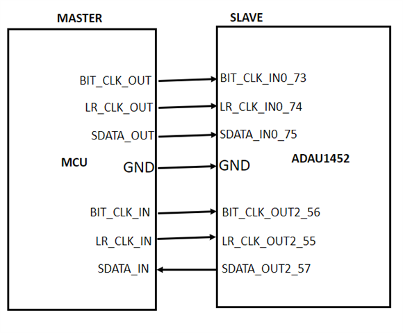
I will explain it with a block diagram and screenshots for setting up the serial in/out ports and ASRC. Please make sure and verify that you have done all of these.
Hardware connection:
Four wires needed for the input from the MCU to the DSP.
MCU DSP
1) BCLK >>> BCLK_IN0
2) LRCLK >>> LRCLK_IN0
3) SDATA >>> SDATA_IN0
4) GND >>> GND
You have to physically connect these wires from an MCU to the Serial input port.
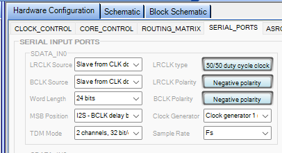
Serial input port setting:
You should have to set "Slave from clock domain 0" for both BCLK and LRCLK as shown above. It means that we need to give the serial clock signals externally to the serial input port 0.
Then, if you are using other serial input ports as a slave then you don't need to give external clocks. You will simply set all the three serial input port 1,2,3 as 'slave from clock domain 0'. It will work. For that serial input port 0 must be clocked externally. (BCLK,LRCLK).
Note that, there are no connections between serial input and output ports. They are totally independent.
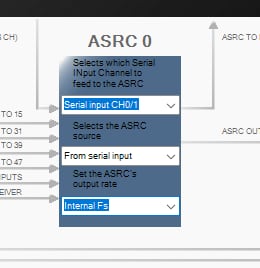
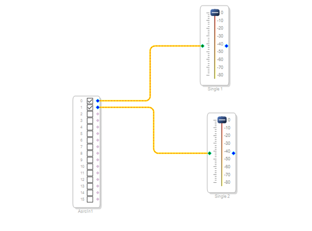
ASRC setting:
Get the inputs from ASRC and use it in your schematic as shown above.
Serial output port:
MCU DSP
1) BCLK >>> BCLK_OUT2
2) LRCLK >>> LRCLK_OUT2
3) SDATA <<< SDATA_OUT2
4) GND >>> GND
You have to physically connect these wires from serial output port to MCU.
You should have to set "Slave from clock domain 2" for both BCLK and LRCLK as shown above. It means that we need to give the serial clock signals externally to the serial output port 2. Then, if you are using other serial output ports as a slave then you don't need to give external clocks. You will simply set all the three serial output port 0,1,3 as 'slave from clock domain 2'. It will work. For that serial output port 2 must be clocked externally. (BCLK,LRCLK)
Make sure that the MSB positions, sample rates are same at both sides.
Kindly do reply if you need any clarifications.
Regards,
Harish

Thank you a lot! Since from the MCU side the communication is full-duplex (same LRCLK and BCLK is used but separate SDATA in and SDATA out), I will just physically connect the respective LRCLK and BCLK pins on the DSP.
So BCLK and LRCLK on the input and output on the DSP will be just shorted.
Please log in to reply.