Single Level Detector w Numeric Display component display error at some input signal level in SigmaStudio
Hi ADI team
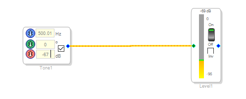
I found the Level Detector w Numeric Display component in the SigmaStudio display a error value at some input signal level. Below is my DSP project for test Level Detector w Numeric Display component base on ADAU1452EVA, use tone component as signal source.
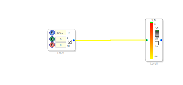
1. Input 0db signal, Level Detector w Numeric Display component display -3db. that is correct, since it display RMS value, and 0db input signal is peak value.
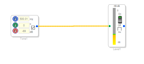
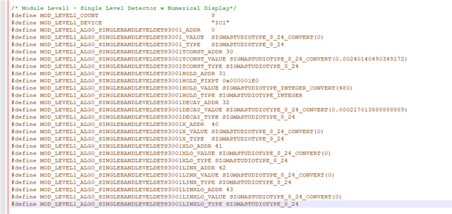
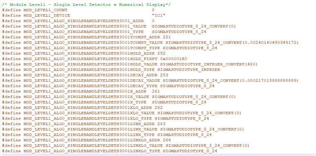
2.Input -69db signal, Level Detector w Numeric Display component display -69db. This display is not correct, it should display -72db. Check the Level Detector w Numeric Display component registers and capture SPI bus data via logic analyzer, the register of MOD_LEVEL1_ALG0_SINGLEBANDLEVELDETS3001X_ADDR and MOD_LEVEL1_ALG0_SINGLEBANDLEVELDETS3001XLO_ADDR are fixed at 0x00000001 and 0x7FFFFFFF. Didn't found any change all the time. it seem some calculate error in the DSP.
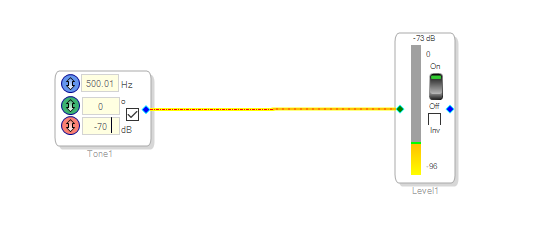
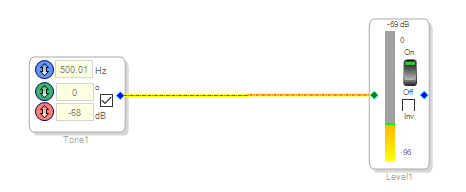
Do more test, input signal level -67db, -68db, -69db are diplay the same value -69db on the Level Detector w Numeric Display component. And then -70 db input signal level get the correct value -73db display. This issue only occur near -67db input signal level, it seem have some error when convert data between high word and low word of the level calculate registers.
Audio Signal Processors
adau1452
Audio Products
software
sigmastudio
SigmaDSP Audio Processors
SigmaStudio v4.7
Show More


Hello,
The meter is reading the RMS value not the peak value so that is why you see -3dB when feeding it a 0dBFS signal. So this is normal and you understood that.
At -69 is where the issue between the high and low comes into play. This meter is not designed to be a laboratory meter but only give you a basic idea of what the level is. So there is some round off errors going on when the level gets really low. This is most likely what you have found. Also, make sure the high pass filter is turned on if you are coming from an ADC. There can be some significant DC offsets that will skew the level reading. In your tests you are using the oscillator module so I know this is not the issue when you performed the tests. I am just mentioning this for other people.
What are your needs for your application? If you require an accurate meter 70dB down? Then using your MCU then you can use both of the data words to get the full resolution. If you are using SigmaStudio then you could use other methods. Does your program need to use this level value?
Dave T
Hi Dave
Thanks for your quick reply!
My application have Guitar input,BT input and USB audio, the requirement is monitor the Guitar input signal level and trigger USB audio record the Guitar signal when input signal level trigger some threshold(like -70 db). In my application I use a STM32 MCU to read level register via SPI bus. I have test other methods like Signal Detection,Running Average: Single Level Detector,Direct Read: Single Level Detector,all of them can get the correct level in the range -60 db to -70 db and meet my requirement. I just be curious why the Level Detector w Numeric Display component can't get the correct level n the range -60 db to -70 db, is it any calculate in my MCU program. Finally I use ADAU1452 EVA to verify this component and found the level display not correct in the level range -60 db to -69 db(the right display level should be input signal level minus 3 db). As below picture display, input -67 db and -68 db get the same level -69 db.
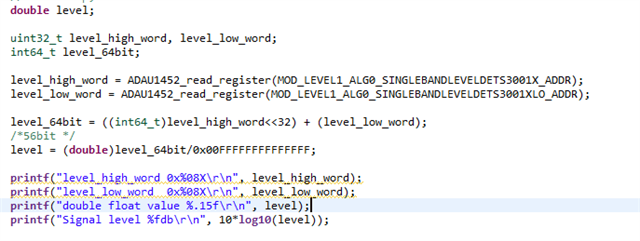
Beside this issue, there is another issue in my MCU program. MCU can't get the correct level when input signal level is below -70 db, is any mistake in my program? As i know, the level register is 8.56 fix point value, so I convert it to a double float value and then convert it to db. if I only use the high word to convert to db, it can get the correct convert value in range 0 db to -60 db. That is what i confused. Below is my program that use full resolution convert to db and register address in my application.
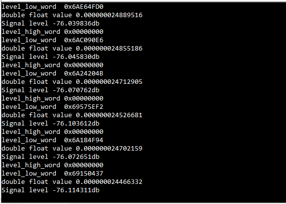
The test result after MCU convert and the input signal level -70 db, get the -76 db calculate value in my program.
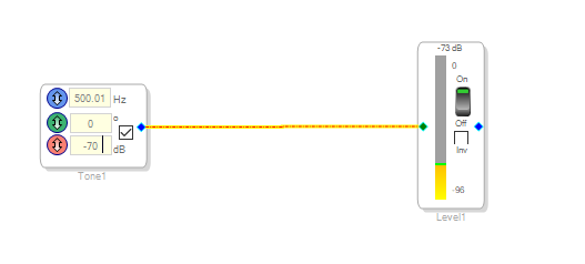
On the ADAU1452 EVA board, input -70 db signal get the correct display -73 db.
Please log in to reply.