MCLK issue and replicable Adau chip
Hello every , and Hello DAVE,
I look into this ADIEngineerZone for long time, but this is my first time post here.
I have a Bluetooth project using Adau1761, the Bluetooth chip cannot generate MCLK to the adau1761 and the BT chip cannot be i2S slave (it must be MASTER). Basically 1761 cannot work without MCLK. Therefore, a local 12.288M crystal was added to adau1761 MCLK input and set the i2S serial port to work in slave mode. Now the DSP has the core clock to run and start to work, but the audio was not perfect. Most of the time it is clean but it has some random ticking noise. I am assuming that was during to unsync MCLK from different source and the LRCLK is somehow unsync with the i2S +1 delay standard. It randomly creates ticking noise.
unfortunately, adau1761 require minimum 8MHz MCLK input signal. The 3.072MHz Bclk signal from BT master cannot be the MCLK for DSP and PLL upscale to 49.152MHz core clock. The same treat can work on Adau 1701 because it can accept lowest 3MHz MCLK input. The adau1761 just cannot do it. I have already verify the adau1701 can work in this way.
My question is, is there any way can make 1761 accept 3.072M bclk as an MCLK signal and then PLL to core frequency ?
if no, is there any compatible chip can work this way ? adau1701 can sure working in this way, just the power dissipation is 10 times higher than adau1761. I really like the 1761 low power feature.
Audio Signal Processors
hardware
mclk
i2s
noise
SigmaDSP Audio Processors
adau1761
slave
adau1701
Show More
Hello KennyC,
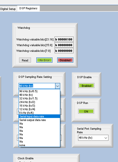
A quick solution will be setting the DSP sample to be from serial input port. Below is how you can set it.
Now, we are telling the DSP to use the incoming serial port (slave) clocks as the DSP sample rate clock.
You use the crystal to drive the internal system clock, but you synchronize the DSP core to run the program only when the serial port data has arrived and is ready. In our newer DSPs we call this the start pulse. This is the clock that tells the core to start running the program.
This will hopefully take care of the click and pop noise.
There is a limitation with this method, but it will not be an issue unless you use almost 100% of the DSP resources. Since the crystal provides the core clock and sample rate is coming from different source, there will be a small drift between these two clocks, but it will not be an issue if you are well below 99% of the DSP resources (MIPS).
Regards,
Harish
Thank you Harishgowtham Bro. Let me try it. This method seems very promising and can save my life. ( finger crossed )
Hello Harishgowtham, I tried this method but it is not 100% guarantee. sometime can still hear the "click" noise. It was really random like once per 10 or 20 seconds. I started thinking it was another issue out of MCLK.. And I think my project is really simple, an EQ, a Crossover, a Dynamic bass unit, a compressor, some adder blocks before the DAC output. it shouldn't overdriving the DSP to over 60% MIPS.
Hello KennyC,
This will have nothing to do with the program itself but this is a clocking issue. Clocking issues end up being an analog issue with the clocks. I always say with digital audio it still comes down to analog! There are so many little things that can be the problem and I have nothing in front of me to help point you in one direction. You will have to attach a high quality scope to the clocks and data and study the rise and fall times and the edge timing between the clocks. I talk about how to setup the scope and a little about how it should look in this post but this post is not geared towards showing good or bad signal integrity and timing.
(+) How to Take Meaningful Screenshots of I2S Audio Signals - Q&A - Audio - EngineerZone
Signal Integrity is a huge subject. There are a lot of factors, chip output pad drive strengths, Drive impedance, bus or trace impedance, trace capacitance, input pin/pad capacitance, length of the traces, how many vias, the layer stackup which effects stray capacitance etc., If you have jumper wires or ribbon cables that is almost always a limiting factor and cause for issues. When using the scope where you place the probes will be important. Place them as close to the receiving serial port as possible. Ultimately you want see what the edge timing and levels are where the receiving device is seeing them.
With this SigmaDSP core, as long as you have a valid and correct frequency of MCLK and you setup the PLL to produce the correct internal system clock, the DSP program is a deterministic program. This means it will run EXCACTLY the same way every time. this core has very few ways that the number of instructions differ from frame to frame. This DSP core does have looping instructions but nothing to be concerned with unless you are at like 98% usage and the compiler tries to estimate this. So this is why I am saying this is not a program issue but a clock/data transmission issue.
Dave T
Thank you for the reply DAVE. I will try your suggested measurement method in the link first. I know this is an clocking issue because the master device (BT) doesn't provided MCLK. DSP has to own its local Crystal MCLK but like i said, the "click" noise was really random once per 10 or 20 seconds. The noise was not like sparkling or the vinylic player. It is difficult to believe the i2s traces are bad. I tried our best to route those traces short, shielded, ground protected layering and within a clean area smaller than the size of thumbnail.
the best scope i have is the agilent infiniiVision MSO7104B 1GHz 4 GSa/s. I wish i could have something to share later.
Finger crossed.
Please log in to reply.