Parametre generator for ADAU1761 Peaking filter
Hello EZ - i am currently writing a C driver for several future products and i have reached a challenge i need help with:
Assignment:
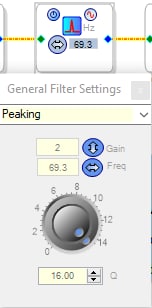
The hardware guys have made an implementation that uses these filters and they want me to change the frequency, which i understand to be the center frequency, f0, on the fly in firmware.
What i have tried:
I have had success with safeloading parametres to several other blocks in sigma studio, implemented on an MCU setting up the ADAU1761.
My approach has been changing parametres in the sigma studio block, seeing what is written over SPI, figuring out the number format for every parametre and the corrosponding addresses for them.
These filters clearly implement a lot of math based of off the numbers and generates parametres that are unrecognizable compared to the input.
this is what i see:
SS box numberfield input = array_of_output
69.3 = 0x00,0x00,0x0b,0xb1, 0x00,0x00,0x00,0x00, 0xff,0xff,0xf4,0x4f, 0x00,0xff,0xea,0xbb, 0xff,0x80,0x12,0c93
0 = 0x00,0x00,0x00,0x00, 0x00,0x00,0x00,0x00, 0x00,0x00,0x00,0x00, 0x01,0x00,0x00,0x00, 0xff,0x80,0x00,0x00
96000 = 0x00,0x2f,0x32,0x91, 0x00,0x00,0x00,0x00, 0xff,0xd0,0xcd,0x6f, 0x00,0xb5,0x04,0xf3, 0xff,0xca,0xfb,0x0d
1000.1 = 0x00,0x00,0xa8,0x14, 0x01,0x00,0x00,0x00, 0xff,0xff,0x57,0xec, 0x00,0xfc,0xc6,0x7c, 0xff,0x81,0x0B,0x05
7.8 = 0x00,0x00,0x01,0x51, 0x00,0x00,0x00,0x00, 0xff,0xff,0xfe,0xaf, 0x00,0xff,0xfd,0xeo, 0xff,0x80,0x02,0x17
Searching the web and researching with AI i found out that there's likely some formula for calculating the parametres of off fs, f0, Q and Gain.
i know that gain, samplerate, and Q are constant at
Gain=2
samplerate=48000
Q=16
Only my center frequency is changing. Cant make my code produce the parametres properly with what i have tried so far.
What i request
A piece of code, preferabilly in c, that can produce the 20 bytes of parametres from values that are available to me, that works with the peaking filter on ADAU1761. This would help a lot!
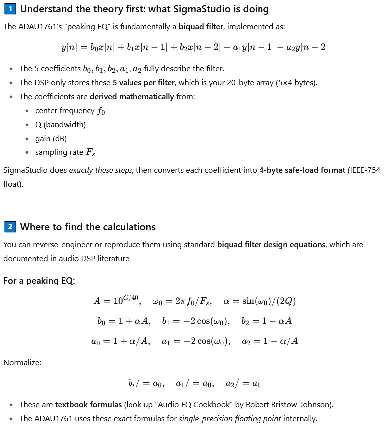
Alternatively i would request help creating these which probably starts as outlaying all of the maths involved. ChatGPT tells me this:
-this might be a good or bad place to start? i suspect there's something in the datasheet or some other documentation i havent discovered -.-
Audio Signal Processors
software
4.7 build 0 rev 1831 4/5/2022
parameters
sigmastudio
SigmaDSP Audio Processors
adau1761
peaking filter
Show More
Hello ClkVictim,
Yes, these are digital filter coefficients for an IIR filter. There are tons of posts about this on the forum.
I wanted to point you to the Wiki entry about these but it has been updated to SigmaStudio+ and got rid of the details for this Sigma200 core. Ugh!
General 2nd Order Filter [Analog Devices Wiki]
But, there are posts on the forum but let me ask you some more questions about your application first.
Do you know what the new center frequencies are?
Will it be any random number or just one of a fixed set?
Because, you can do a couple of different things.
1) You could enter these frequencies and then look at the parameters listed in the Capture window and copy those down.
2) We also have index selectable filters where you can select from a set number of filters. But, this takes up more instructions and memory space.
This DSP cannot calculate its own filter coefficients like the Sigma300/350 cores can do... Bummer.
Let me know what your options might be?
Thanks,
Dave T
Some more info:
(+) Calculating Filter Coefficients to Store in a Microcontroller - Documents - SigmaDSP Processors & SigmaStudio Dev. Tool - EngineerZone
This one is about a different filter but might have some info for you:
(+) question about "Calculating Filter Coefficients to Store in a Microcontroller" - Q&A - SigmaDSP Processors & SigmaStudio Dev. Tool - EngineerZone
Dave T
"Do you know what the new center frequencies are?
Will it be any random number or just one of a fixed set? "
The center frequencies is currently a standard list with 50-ish standard frequencies and uncountable costum frequency lists that costumers could choose arbitrarily - making their own frequencies if that is their wish.
We do not wish to be limited by having everything -that we currently imagine as a desired center frequency, written in a lookuptable.
But it is my backup plan in case i cannot figure this out.
It will be a very large lookup table and new costumer specified frequencies would mean new firmware every time -.-
Finding a way to, in the MCU firmware, calculate the parametres with the center frequency being the only variable input of the peaking filter should be worth 3-4 days of work if it turns out to be that challanging.
I will probably run into this again as i write drivers for the other blocks as well so solutions found here will probably pay dividends.
ill take a look and try to concoct some code based of off this.
I have looked a little on the way-back machine but i could use a little additional guidance if you remeber the specific link to the entry in the old wiki or remember which hyperlink on the bewsite.
The way back machine is very slow - it's not viable for perusing.
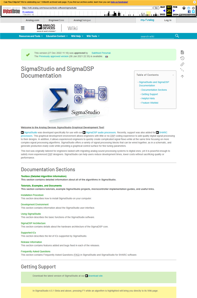
Discovered that the wiki itself has some kind of way back function in previously approved versions of the sites, in which i found this:
wiki.analog.com/.../generaleq2ndorder
oh my god, thats a lot. But this might be the only way -.-!?
Hi ClkVictim and Dave,
As Dave mentioned, there's a number of posts on this subject. Some include a spreadsheet BrettG created and I expanded. Searching the forum made me dizzy so I'll just attach it again below. It's relatively easy to build C code from the formulas in the spreadsheet, yet here's some tips:
If your implementation involves choosing among discrete frequencies (example: 1/6 octave steps) it makes sense to pre-calculate some variables, placing them in a lookup table in your C code. Of course, if you're uC is quick enough and your compiler has a complete set of CORDIC log and trig functions, you could just have it calculate everything on demand.
To test a coefficient set: manually type the coefficients into the IIR Coefficient version of the Second-Order Filter and run a Stimulus-Probe graph.
The definition of a and b coefficients are unfortunately not fully standardized; I've seen them both ways in the literature.
If a filter's response makes no sense at all, try flipping the signs of the two a coefficients. The IIR Filter implementations for at least some of the chips use a coefficients with flipped signs to save instructions.
Best regards,
Bob
XLS

Interesting - i had found the original file without your expansion, on the wiki, i think, but the coefficiants calculated on the present filters didnt match what's produced in sigma studio, which i assume is OG cannon.
If this expanded sheets peaking filter works - i'll be so happy. Either way, Thank you so much for this BOB.
I'll do a comparison with the Sigma studio generated coefficiants and will return with a result here - so exciting!
If nothing else, i can probably take inspiration from the math and maybe tweak it until it fits.
The peaking filter produces really close to the values in sigma studio - with the A's sign swapped while B0&B2 are around 25% too large -.-? and this scaling increases with frequency. I have only tested in the range 0-250. but i realise that the coefficiants are for implementing a peaking filter using the IIR filter whereas i am using the peaking filter variant in sigma studio. And i have no say to change it into the IIR variant.
this might be still be usable for me with an added scaling factor. if i can hit it precisely with a scaling-scaling factor xD
Thank you Bob, not the correct solution, but way better than the one before.
Please log in to reply.