How to write custom processing blocks.
Hello: I need to implement a full wave integrator. This nonlinear device does the following...
Integrates the absolute value of the audio input, and the output is reset to zero when the input has a zero crossing with a positive slope. I cannot seem to be able to construct this with the standard building blocks provided in the SigmaStudio ADAU176x tool set. I know there is a value cross detector that can output a pulse at every zero crossing, but does not take into account the slope of the signal. Further it is a pulse and I cant really see any useful block to preform the "reset to zero" based on the output pulse. There is a absolute value arithmetic operator block that I believe will handle the absolute value of the input. There is also no integrator block, but I guess I could do that with a first order low pass processing block. If this can not be done buy using any combination of the standard blocks, what is the procedure i.e. tools / documentation / instruction set references, etc. etc. to “roll my own algorithm” ?
Audio Signal Processors
sigmastudio
SigmaDSP Audio Processors
adau1761
Hello,
many users made the same request in order to write their own processing blocks,
but the answer is that this cannot be done.
If Analog Device's sigma dsp staff thinks that your request may have a broad range of
application or interest, maybe they will implement a new block in the future sigmastudio
releases, on the contrary you must try to wire the existing blocks together in order to
get what you need.
I'm not that sigmastudio master, but i think that what you asked for can be built
with existing blocks.
It is a good idea to use the filter as an integrator, but you should clear its internal status
on the positive slope of the input signal, so you have to realize it yourself.
I can suggest to use something like this:
Yn=Yn-1* k + (1-k)*x
where Y is the output, x is the input, k, ranging from 0 to 1, is the time constant.
You can then clear it, zeroing the Y(n-1) value.
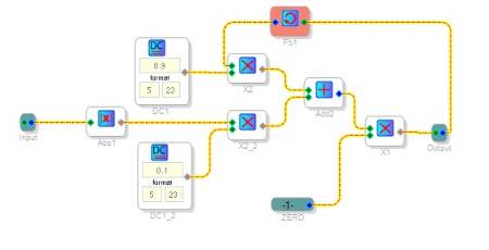
This block should work, it is programmed with a time constant equal to 0.9
(note the other fixed value is 0.1, that is 1-0.9) and when the "Zero" input
goes to zero, the accumulator is cleared.
You have to drive this line with a zero going pulse triggered when the input signal
crosses the zero line with positive slope, for the rest of the time it must be 1.
At present, there is no way to directly write code for the SigmaDSP. We are considering making that a possibility in the future. For now, if you need a particular function, please let us know the details and perhaps we can suggest a solution, as drugoimir did in the preceding post.
For an intermediate step, it could be funny to be able to create my own processing blocks, using standard sigmastudio blocks, and then
exporting and reuse them into different projects.
Here's a tutorial explaining how to do that!
Thanks so much drugoimir. This is very helpful and I will attempt to implement.
The part I am wrestling with is ...
>You have to drive this line with a zero going pulse triggered when the input signal
crosses the zero line with positive slope, for the rest of the time it must be 1.
I'm trying to think of a way with the existing blocks to be able to do that.
Do you or anyone have any thoughts on that section?
Thanks Again !!
Hi,
you're welcome.
Try the Hilbert transform, you should have on your toolset.
As you know, it gives you a 90° shifted copy of the input signal
over a broad range of frequencies.
When the leading output crosses zero, look at the lagging one: if it is
negative you are crossing zero with positive slope.
Think that this could be done also with a normal delay, the trick is the
same: look when the actual sample is zero and then check the previous
one's value. If it is negative fire your trigger.
The difference between the two is that the first could be very resource
consuming, but it should be very accurate over a broad frequency range.
The second is simpler but to be accurate the delay might be some samples long.
This could lead to false triggers when high frequency passes through.
If this has to be activated only by low frequencies, you could apply a lowpass filter
in front of everything to limit the maximum frequency passing in.
Last idea is that you could combine some one shot trigger with the zerocross detector.
The one shot trigger should be set when the input signal is negative and the filter
reset pulse has to be generated from the boolean-and of the trigger status and the zerocross detector.
On the positive edge the trigger has to be reset so to be triggered again on the negative side of the
waveform.
Any one is good for you?
Bye
Drugo
Hello Drugo / all.
I want to thank you again for your guidance / help etc.
Indeed the Hilbert transform would be too much of a resource drain in the long run.
I like your idea of ...
“Think that this could be done also with a normal delay, the trick is the
same: look when the actual sample is zero and then check the previous one's value. If it is negative fire your trigger.” etc.
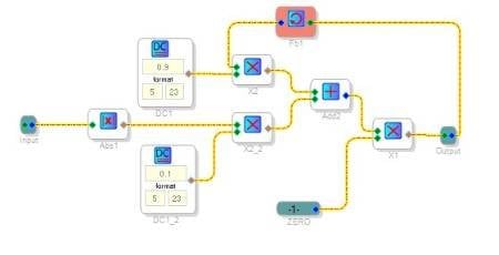
Attached is my schematic of what I have come up with. The lower portion is the zero cross detector with positive slope triggering a zero pulse, otherwise 1.
The top half of the schematic is the integrator as you previously described etc.
I have attached 2 scope traces of the input signal, integrator output and zero cross detector.
In scope picture 1 the integrator is acting as a normal full wave rectifier with a 50Hz sign wave input.
In scope shot 2 the integrator is acting more like what I need i.e. a full wave integrator with a 2000Hz input.
Do you think I need to adjust the time constant equal to 0.9 or ??
Note: as you mentioned I do have a advantage in that this full wave integrator only need to work at low frequencies, I.e less then 200 Hz.
Any thoughts on any of this would be greatly appreciated.
Thanks Again
Fullscreen
cdc33b196fbe589e7df7f5c41109431f.html
Download
<html><head><title>Jive SBS</title></head>
<body><font face="arial,helvetica,sans-serif">
<b>Error</b><br><font size="-1">
An general error occurred while processing your request.
</font></font></body></html>
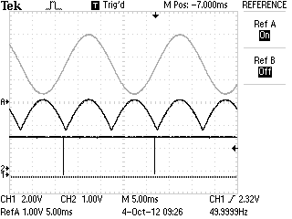
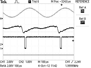
Very good you got it!
It is visible the first part of the rectified halfwave (about 200uS after the reset pulse), then
the second part of the halfwave that raises over the peak value of the previous one, then
the reset pulse that reinitializes the filter: it's a full wave rectifier indeed!
The time constant (0.9) will act both on the final peak value of the full wave integrator
so on its harmonics content: reducing it, you will get more harmonics.
Do you think I need to adjust the time constant equal to 0.9 or ??
It depends on the final result you 're expecting.
If you are designing something like an enhancer/effect, maybe you can make this parameter
variabile, so the user can adjust it according his own taste.
Remember that the other value is simply equal to 1-X, where "X" is the value you choose
as your integrator time constant.
Bye
Drugo.
Can we directly write dsp code for SigmaDSP now?
Hello jaontolt,
Not quite yet but getting closer. I suggest you make friends with your local ADI rep. He/She would know if and when we might have classes near you. It is not a simple thing and support has always been the issue. We just cannot support everyone no matter the skill level.
Dave T
Please log in to reply.