SigmaDSP Two Microphone Beamformer
A new algorithm has been created for the ADAU1761 that will take two microphones and adaptively beamform in order to directionally focus on an audio source in the stereo field. This algorithm will be included in the next SigmaStudio release.
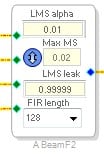
The GUI cell looks like this:
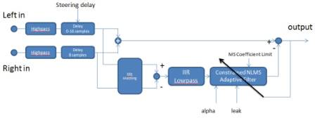
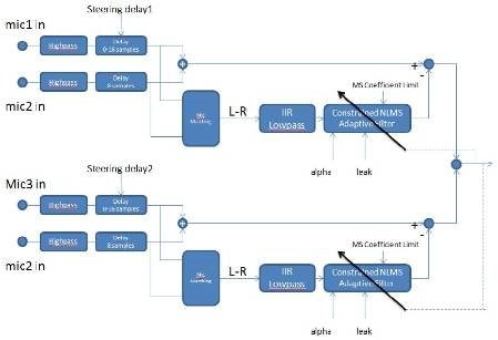
The 2-channel SigmaDSP Beamformer uses a modified version of the so-called “Griffiths-Jim” Beamformer (1). This beamformer can track a single source of off-axis interference and place a null in the directional pattern, pointed at the source of the interference. The Block Diagram of this beamformer is shown below.
The left/right microphone inputs are first applied to a highpass filter to remove DC components. The filter cutoff frequency is 15Hz for Fs = 24KHz.
The “steering direction” is set by the difference in delays between the two inputs. The right channel contains a fixed input delay of 8 samples, and the left channel has a variable delay from 0 to 16 samples, allowing the left channel to either lead or lag the right channel by up to 8 samples. The directional pattern has maximum sensitivity when the outputs of the two delay blocks are the same. The corresponding source angle can be computed based on the sample-rate and microphone spacing. The pin “intermic_delay” should be connected to an external DC source, and is designed so that with 0 input the left-channel delay is equal to the right-channel delay (8 samples). This pin has a sensitivity of 1 LSB per sample delay. If this pin is connected to an external DC source, the numeric format of the DC block can be set to “28.0” so that the inter-mic delay can be entered directly in samples, with values between -8 and +8.
The outputs of the delay blocks are summed in the upper path, and differenced in the lower path. Before the difference operation, a microphone matching algorithm is used that attempts to match the amplitudes of the two microphones. This will result in reduced sensitivity to microphone gain tolerances, but it should be noted that the microphones still need to be tightly matched in terms of phase response.
The difference signal is then applied to an IIR lowpass filter which attempts to pre-compensate the expected rising response of the microphone difference signal, and then applied to an normalized adaptive filter which attempts to remove any L-R components that are present in the L+R signal. In theory the L-R signal should go to zero for signals in the “look” direction, but in practice this does not occur due largely to room acoustics. This can potentially allow the adaptive filter to also eliminate the desired signal. To prevent this, a limit is placed on the maximum mean-square value of the filter coefficients. Since the value of this parameter depends on room acoustics, it is made adjustable by the user. In practice this parameter controls how close the adaptive null direction can be relative to the “look direction”. Smaller values should be used in highly reverberant environments to prevent accidental cancellation of the desired signal. For off-axis interfering signals, the L-R signal is large enough due to the left/right phase differences that the adaptive filter does not need to have a large gain in order to cancel the L-R component, and therefore the mean-square coefficient limit is never reached. A typical value for this parameter is around 0.02.
The normalized adaptive filter also exposes parameters for “alpha”, which controls adaptation speed, “leak”, which controls the LMS coefficient leakage factor, and the filter length which can be set to 32, 64, or 128. These parameters are well-covered in the literature on adaptive filters. Note that the default parameters are set with an assumed sample-rate of 24KHz, and for other sample-rates the value for alpha should be adjusted inversely to the sample-rate. If the “leak” factor is set to 1.0, then the null that forms in a particular direction will persist even when the input signal goes away, whereas if the leak factor is set to, for example, 0.99999, the filter will slowly decay to zero after the signal has gone away. If the leak factor is set too low, the depth of the directional null will be poor.
A pin is also provided to turn on and off the adaptive algorithm. Applying a 0 to this pin turns the adaptive filter off, and “1.0” enables the adaptive filter.
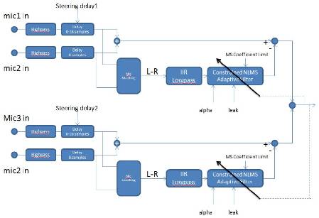
To extend this algorithm to more than two microphones, you can cascade systems as shown below. Note that one microphone (mic 2) has a fixed delay in both upper and lower paths, and the other 2 mics are adjusted relative to mic2 in order to steer the beam. Note that for a 4-microphone systems, up to 3 independent off-axis interfering sources can be tracked and canceled.
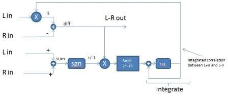
The details of the mic matching algorithm are shown below. Note that the goal of this algorithm is to minimize the correlation between L-R and L+R. For closely-spaced mics this amounts to compensating for gain mismatch, but for larger mic spacing (or for very high frequencies) where the phase difference between the mics becomes large, it may not yield the same result as simple gain mismatch reduction.
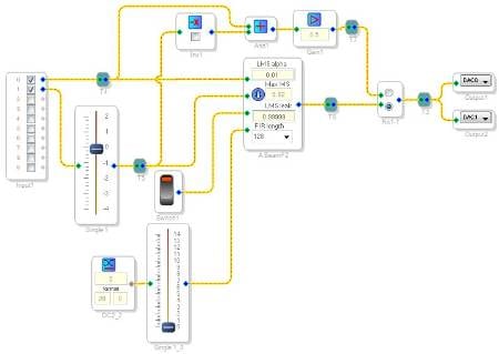
Here is an example of the beamformer in a SigmaStudio project:
Pins
Mic In (top pin): Left channel input (5.23 audio)
Mic In (2nd pin): Right channel input (5.23 audio)
Start/Stop (3rd pin): Turn this on to adapt the target direction of the beamforming. Turn it off to “lock” the directionality at its most recent value. (5.23 logic)
Inter-microphone delay (bottom pin): (28.0 integer, one sample per LSB, between -8 and +8)
Output: The resulting audio output after beam-forming (5.23 audio)
GUI Controls
LMS alpha (adaptation speed)
Max MS (maximum mean-square value limit for filter coefficients, typically 0.02)
LMS leak (controls the "leakage" of the filter when the input signal goes away. Set slightly below 1)
FIR length (length of the filter)
Resource Requirements
Instruction RAM: 189 words
Instructions executed per sample: 189
Data RAM: 175 words
Coefficient RAM: 177 words
Audio Signal Processors
microphone
sigmastudio
SigmaDSP Audio Processors
adaptive
adau1761
SigmaDSP
beamforming
Show More


Is there any information on how to physically place the microphones? What would a typical distance between a 2 microphone system when the delays are equal? I want to test this out with 2x ADMP421s is there anything about these parts that wouldn't be ideal for this situation?
The algorithm was developed with a spacing of about 3 cm, and that is the recommended distance for a "typical" system. Increasing the spacing can give you better directionality, but if the spacing between the microphones is too large, it can result in spatial aliasing, where certain frequencies may be detected at multiple locations. Higher frequencies are more prone to this spatial aliasing problem than lower frequencies.
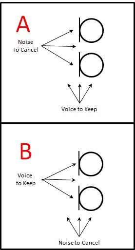
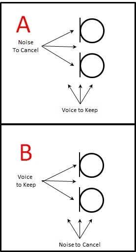
Thank you Brett. Which orientation would work correctly for canceling noise but retaining voice? Thanks again for you help!
If anyone else is interested in some background information Jerad wrote an interesting ADI application note on beamforming:
http://www.analog.com/static/imported-files/application_notes/AN-1140.pdf
Hi Natan,
B is the proper configuration. The audio source can move left or right in the stereo field, and the algorithm should track them. Keep in mind that this is not really a noise cancelling algorithm. It is simply a directional steering algorithm. It creates a kind of cardiod pattern that points the axis of maximum sensitivity in the direction of the signal source (in most cases, that would be a person speaking). While this algorithm does not actually cancel the noise in other directions, it simply is less sensitive to sources that are off-axis from the directional pattern.
Sorry for the heavy use of italics! I hope that was clear.
Interesting, so the NLMS automatically steers the audio pickup depending on power detected in certain directions, or would manual steering using the delays be needed? Pickup would look something like Figure 9 of the Application Note?
When you activate the Start/Stop (3rd pin), the algorithm will begin to automatically detect and steer the algorithm depending on the power detected in certain directions. When you de-activate the Start/Stop, it will then lock the directionality into place. The idea is that if you have some way of determining when a person is speaking, you could only activate the directional steering adaptation when the source is active, and then lock it into place afterwards.
I believe the "inter-mic delay" pin allows fine tuning of the directionality, but I'm unsure of how it should be configured.
I'm not sure which pattern in the application note matches this application. Perhaps Jerad can comment.
According to your comment this algorithm utilizes an array in a Broadside configuration. Although your mention of a cardiod pattern makes me think it should have a pickup pattern which looks more like an Endfire configuration.
The description of this algorithm looks like it says that the number of nulls in the spacial response will be (# of mics - 1). So, for a 2-mic system, there will be one null, like a cardioid pattern.
Note that if the spacing between the mics is 3 cm, then there may be aliasing at frequencies above 11.5 kHz (wavelength at this frequency is about 3 cm). For most applications, especially those capturing voice, this frequency is sufficiently high that the spatial aliasing shouldn't adversely affect performance.
I haven't had a chance to try out this algorithm with our mics yet; I'll have to do that over the next couple of weeks.
Thanks Jerad,
That's my understanding as well, based on my conversation with the algorithm designer. The spatial aliasing issue is only a problem for higher frequencies, like you mentioned.
I appreciate all the help. I am new to beamforming in general and am interested in trying this out. I have some evaluation kits on order for the microphones and will be ready to try it out as well when this is released.
Here is an update from the algorithm designer with some new, useful information:
The block implements a modified form of the "Griffiths-Jim" beamformer. You can search for this on the internet and get lots of information.
The 2 input channels are both delayed, with one channel having a fixed delay and the other a variable delay. The delay is set so that the L-R signal is minimized in the direction that you want to point. Note that the scaling of this input changes with the sample-rate. In other words, if you want to set the algorithm to point in a certain direction, you want to set this delay to a given absolute time-delay, so the number of samples that you need to delay by is different as you change the sample-rate. Note that we use linear interpolation to get sub-sample resolution on the delay control.
After the input delay block, we form sum and difference signals. The difference signal is applied to an adaptive filter and subtracted from the sum signal. The output of this subtraction is the final output of the beamformer.
When the acoustic signal is not at the desired pointing angle, the L-R signal is large, and the adaptive filter can therefore completely remove the L+R signal at the output. If the acoustic signal is at the desired pointing angle, then the L-R signal is 0, and the adaptive filter cannot cancel the L+R signal, so the output = L+R.
In reality, because of reflections in the room, the L-R signal never becomes 0, even when the acoustic signal is at the desired pointing angle. What happens is that the L-R signal becomes small, and the adaptive LMS filter coefficients become large as the filter attempts to cancel the L+R signal. This is not desirable because it means that the output will be zero when the acoustic signal is at the desired pickup angle in a slightly reverberant room.
So in order to make sure that the adaptive filter cannot cancel the L+R signal when the L-R is small, we detect when the filter coefficients are large, by looking at the mean-square sum of the filter coefficients. When this ms sum exceeds some threshold (which is set in the studio GUI) then we switch from a conventional LMS update equation to a "leaky" update equation, where the leak factor (typically very close to 1.0) is set on the SigmaStudio block. By using this technique the limit on the filter coefficients is "soft" and does not cause any sudden changes in the filter coefficients.
This has the effect of limiting the maximum gain that the adaptive filter can achieve. So you can think about the whole algorithm like this; the adaptive filter is always trying to cancel the output signal, but when acoustic input as at the desired angle, the input to the adaptive filter becomes small, and by limiting how much gain the filter can achieve, we prevent the adaptive filter from canceling the L+R signal.
The setting of these parameters depends a lot on how reverberant the room is, and how close the source is to the microphone (both of these affect the direct-to-reverberant ratio). In general, a far-away source in a reverberant room is a very difficult situation, and we don't think this algorithm works very well in that situation.
Hi,Guys,
Where's the example mentioned above?
Master, may I ask if this can achieve circular array beamforming?
Please log in to reply.