Clarification on serial I/O in ADAU144x
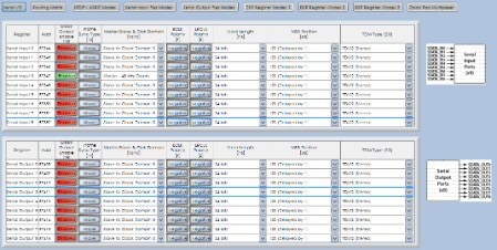
I'm trying to verify my understanding that for ports which have both an input pin & output pin (SDATA_IN[3-8]/SDATA_OUT[3-8]), both the input AND output can be used simultaneously. E.g. I can use both SDATA_IN4 and SDATA_OUT4 at the same time. The requirement for allowing this is that clock domain 4 must be a slave, given:
Although a clock domain in slave mode can clock an arbitrary
number of serial ports, a clock domain in master mode can only
clock a single serial port. For Clock Domains[2:0] and Clock
Domains[11:9], the corresponding serial port is fixed as an input
or output. For assignable clock domains (Clock Domains[8:3]),
the corresponding serial port can be either an input or output,
depending on the setting of the clock pad multiplexer register
Is my above statement true? So in a system with a whole bunch of inputs, a whole bunch of outputs, and the DSP is the master of all clocks, I could tie all input devices off LRCLK0/BCLK0, and have all my inputs be slaved off of that (clock domain 0). For the outputs I could connect just LRCLK9/BCLK9 and slave the outputs from clock domain 9. Could you take it further and only use LRCLK3/BCLK3 (clock domain 3) and make everything (all input devices and all output devices) slaved from that? Configure the system as shown, only use the LRCLK3/BCLK3 pins, and still be able to use SDATA_IN[0-9] AND SDATA_OUT[0-9]?
I feel like there's something I must be not understanding properly. Thanks,
-- Ryan
Audio Signal Processors
adau144x
adau1446
sigmastudio
SigmaDSP Audio Processors
SigmaDSP
Show More

Hi Ryan,
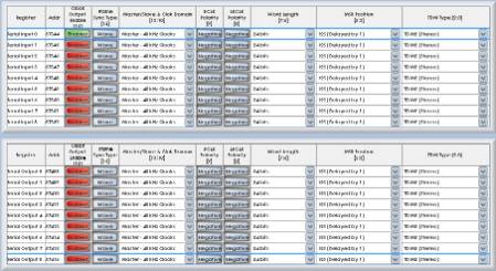
If all of the serial ports are masters, then simply set the "Master/Slave" control for every serial port to "Master - 48 kHz Clocks". This will mean that they are all synchronous to the internally generated 48 kHz clock pulse. You only need to output those clocks on one BCLK/LRCLK pair, so you can pick any one you want, and enable its "Clock Output Enable" bit.
If there are no slave ports, then there's no need to connect any other clock pins externally or to change any other settings.
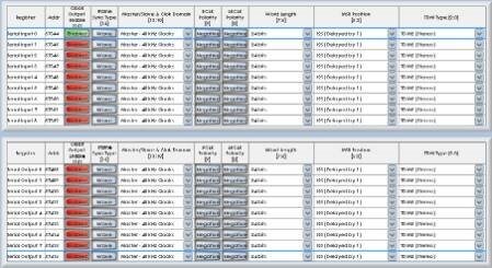
The following settings will configure all pins (SDATA_IN[0-9] and SDATA_OUT[0-9]) to operate in master mode. The LRCLK/BCLK clocks will be output from LRCLK0 and BCLK0. All other clock pins (LRCLK/BCLK[1-11]) will be inactive.
Thanks Brett. My confusion came from the statement "a clock domain in master mode can only clock a single serial port". So how in your example can both serial output 3 and serial input 3 (which should both be on clock domain 3) be masters?
Thanks,
-- Ryan
Hi Ryan,
That statement is indeed misleading. Perhaps it makes sense to think about this in a different way.
You can imagine that there are three sample rate clock generators inside the chip. They generate 48 kHz, 96 kHz, and 192 kHz for the LRCLK pins (of course, you can scale those rates down slightly by slowing down the master clock). Bit clock signals can be generated from those sample rate clocks based on the number of channels on a serial port. For 2 channels, the bit clock rate is 64 times the sample rate; for 4 channels, the bit clock is 128 times the sample rate, et cetera...
Any serial ports set to master mode will be clocked internally from one of those three sample rate clock generators (which are all synchronous to each other), and the BCLK for the respective serial port pin will be generated based on the channel setting for that port.
So, if you have several serial ports operating at the same sample rate in master mode, each corresponding LRCLK pin would output the exact same signal. If the number of channels for each serial port is the same, then the BCLK would also be the exact same signal for each serial port.
In that case (like your use case), then you can simply enable one of those LRCLK/BCLK pin pairs and route those signals on the PCB to the other ICs that need them. Other LRCLK/BCLK pin pairs for master serial ports can be disabled, since they are generating redundant signals.
However, if the sample rate settings or channels per frame settings for each serial port are different, then the LRCLK and BCLK frequencies will differ for each serial port. In this use case, the statement "a clock domain in master mode can only clock a single serial port" is true.
I guess the statement should actually read: "a clock domain in master mode can only clock the serial ports that correspond to its sample rate and channels/frame settings".
Does that make sense?
Thanks for pointing this out. It is indeed a bit difficult to understand.
Ah! That makes perfect sense now. Thanks for explaining it so clearly.
-- Ryan
Please log in to reply.