Configuration of ADAU1467 multipurpose pins MPx
Hello,
I am using EVAL-ADAU1467Z and SigmaStudio+ 2.3.0. In the user guide, one can read that MP15, MP14 and MP7 are connected to DIP Switch S3. These pins are dedicated IO pins, i.e. not multiplexed with any other signal. However, I am struggling to configure them in SigmaStudio.
What is the difference between "Multipurpose" and "Multipurpose 1"?
Both sections seem to list the MP pins but with different naming, e.g. MP0_x vs. MP0_x1. Section "Multipurpose" lists MP pins from 0 to 13. "Multipurpose 1" lists MP pins from 0 to 11. MP14/MP15 are nowhere visible....
Best regards,
Ak
Audio Signal Processors
Datasheet/Specs
adau1467
EVAL-ADAU1467Z
sigmastudio
SigmaDSP Audio Processors
gpio
configuration
Show More
Hello AK,
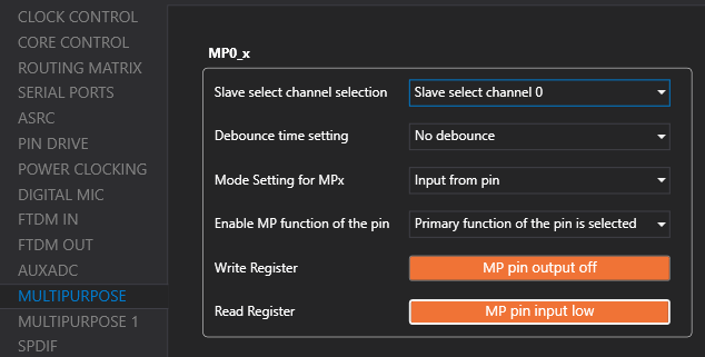
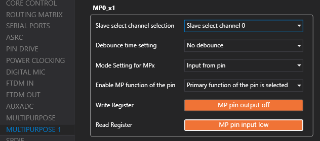
The ADAU1467 has 26 multipurpose pins. The first 14 pins are listed on page 1 (Multipurpose), and the remaining 12 pins are listed on page 2 (Multipurpose 1) please refer to the below table.
Multipurpose Pins
Address
Register
SigmaStudio+
Description
0xF510
MP0_MODE
MP0_X
Multipurpose Tab
0xF511
MP1_MODE
MP1_X
0xF512
MP2_MODE
MP2_X
0xF513
MP3_MODE
MP3_X
0xF514
MP4_MODE
MP4_X
0xF515
MP5_MODE
MP5_X
0xF516
MP6_MODE
MP6_X
0xF517
MP7_MODE
MP7_X
0xF518
MP8_MODE
MP8_X
0xF519
MP9_MODE
MP9_X
0xF51A
MP10_MODE
MP10_X
0xF51B
MP11_MODE
MP11_X
0xF51C
MP12_MODE
MP12_X
0xF51D
MP13_MODE
MP13_X
Multipurpose 1 Pins
Address
Register
SigmaStudio+
Description
0xF5C0
MP14_MODE
MP0_X1
Multipurpose 1 Tab
0xF5C1
MP15_MODE
MP1_X1
0xF5C2
MP16_MODE
MP2_X1
0xF5C3
MP17_MODE
MP3_X1
0xF5C4
MP18_MODE
MP4_X1
0xF5C5
MP19_MODE
MP5_X1
0xF5C6
MP20_MODE
MP6_X1
0xF5C7
MP21_MODE
MP7_X1
0xF5C8
MP22_MODE
MP8_X1
0xF5C9
MP23_MODE
MP9_X1
0xF5CA
MP24_MODE
MP10_X1
0xF51D
MP25_MODE
MP11_X1
Additionally, I have attached an example project that utilizes the onboard EVAL-ADAU1467Z DIP switch and LED for reference.
Please let me know if you need any further details.
ON BOARD ADAU1467 MP PIN EXAMPLE.zip
Regards,
Harish
That was very helpful, it works now, thanks Harish!
Please log in to reply.